
User Manual


54 DS992F1
CS53L30
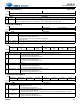
7.26 ADC1 Noise Gate Control
7.26 ADC1 Noise Gate Control
Address 0x28
R/W
76 5 43210
ADC1B_NG ADC1A_NG ADC1_NG_BOOST ADC1_NG_THRESH[2:0] ADC1_NG_DELAY[1:0]
Default00 0 00000
Bits Name Description
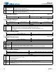
7,6 ADC1x_NG ADC1 noise gate enable for Channels A and B. Enables independent noise gating for Channels A and B if ADC1_NG_
ALL = 0. This bit has no effect if ADC1_NG_ALL = 1
0 (Default) Disable noise gating on Channel x
1 Enable noise gating on Channel x. If a channel’s signal amplitude remains below the threshold setting (refer to ADC1_
NG_THRESH) for longer than the attack delay (debounce) time (refer to ADC1_NG_DELAY), noise gate muting is
applied to only that channel.
• Noise gate muting is removed (released) without debouncing when the signal level exceeds the threshold.
• Noise gate attack and release rates (soft-ramped as a function of Fs or abrupt) are set according to DIGSFT on p. 50.
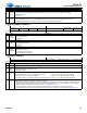
5 ADC1_NG_
BOOST
ADC1 noise gate threshold and boost for Channels A and B. These fields define the signal level where the noise gate begins
to engage. For low settings, the noise gate may not fully engage until the signal level is a few dB lower. Sets threshold level
(±2 dB) for Channel A and B noise gates. ADC1_NG_BOOST configures a +30-dB boost to the threshold setting.
4:2 ADC1_NG_
THRESH ADC1_NG_THRESH
000
001
010
011
100
101
110
111
Minimum Setting (ADC1_NG_BOOST = 0)
(Default) –64 dB
–66 dB
–70 dB
–73 dB
–76 dB
–82 dB
Reserved
Reserved
Minimum Setting (ADC1_NG_BOOST = 1)
–34 dB
–36 dB
–40 dB
–43 dB
–46 dB
–52 dB
–58 dB
–64 dB
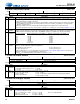
1:0 ADC1_NG_
DELAY
Noise gate delay timing for ADC1 Channels A and B. Sets the delay (debounce) time before the noise gate mute attacks.
Time base = (6144 x (MCLK
INT
scaling factor))/MCLK
INT
00 (Default) 50 x (time base) ms
01 100 x (time base) ms
10 150 x (time base) ms
11 200 x (time base) ms
MCLK
INT
scaling factor is 1, 2, or 4, depending on Fs
INT
and the MCLK_INT_SCALE setting. Table 4-2 lists supported
configurations and their corresponding MCLK
INT
scaling factors.
For MCLK
INT
= 6.144 MHz and MCLK_INT_SCALE = 0, time base is 1 ms.
7.27 ADC1A/1B AFE Control
Address 0x29–0x2A
R/W
76543210
ADC1A_PREAMP[1:0] ADC1A_PGA_VOL[5:0]
ADC1B_PREAMP[1:0] ADC1B_PGA_VOL[5:0]
Default00000000
Bits Name Description
7:6 ADC1x_
PREAMP
ADC1x mic preamp gain. Sets the gain of the mic preamp on Channel x.
00 (Default) 0 dB (preamp bypassed)
01 +10 dB
10 +20 dB
11 Reserved
5:0 ADC1x_
PGA_VOL
ADC1x PGA volume. Sets PGA attenuation/gain. Step size: ~0.5 dB.
01 1111–01 1000 +12 dB …
00 0001 +0.5 dB
00 0000 (Default) 0 dB
11 1111 –0.5 dB …
11 1010 –3.0 dB (target setting for 600-mVrms analog-input amplitude)
…
11 0100–10 0000 –6.0 dB
7.28 ADC1A/1B Digital Volume
Address 0x2B–0x2C
R/W
76543210
ADC1A_VOL[7:0]
ADC1B_VOL[7:0]
Default00000000
Bits Name Description
7:0 ADC1x_
VOL
ADC1x/DMICx digital volume. Sets the ADC1 or DMIC signal volume of on Channel x based on the input source selected
(see Table 4-5). Step size: 1.0 dB
0111 1111–0000 1100 +12 dB
0000 1011 +11 dB …
0000 0000(Default) 0 dB
1111 1111 –1.0 dB
1111 1110 –2.0 dB …
1010 0000 –96.0 dB
1001 1111–1000 0000 Mute