
User Manual


DS992F1 53
CS53L30
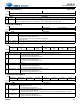
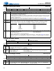
7.24 ADC1/DMIC1 Control 2
1DMIC1_
SCLK_
DIV
DMIC1 clock divide ratio. Selects the divide ratio between the internal MCLK and the digital mic interface clock output.
Section 4.5 lists supported digital mic interface shift clock rates and their associated programming settings.
0 (Default) 64•Fs
int
1 32•Fs
int
0CH_
TYPE
Input channel type. Sets the capture-path pins to be either all analog (analog mic/line-in) or all digital mic.
0 (Default) Analog inputs. Do not connect digital mic data lines to any of the capture-path pins when selected.
1 Digital inputs. Do not connect analog source to any capture-path pins when selected.
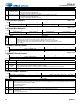
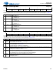
7.24 ADC1/DMIC1 Control 2
Address 0x26
R/W
76543210
ADC1_
NOTCH_DIS
— ADC1B_INV ADC1A_INV —
ADC1B_DIG_
BOOST
ADC1A_DIG_
BOOST
Default00000000
Bits Name Description
7 ADC1_
NOTCH_
DIS
ADC1 digital notch filter disable. Disables the digital notch filter on ADC1.
0 (Default) Enabled
1 Disabled
6—Reserved
5,4 ADC1x_
INV
ADC1x invert signal polarity. Configures the polarity of the ADC1 Channel x signal.
0 (Default) Not inverted
1 Inverted
3:2 — Reserved
1,0 ADC1x_
DIG_
BOOST
ADC1x digital boost. Configures a +20-dB digital boost on the ADC1 or DMIC signal on Channel x, based on the input source
selected (see Table 4-5).
0 (Default) No boost applied
1 +20-dB digital boost applied
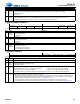
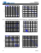
7.25 ADC1 Control 3
Address 0x27
R/W
76543210
— ADC1_HPF_EN ADC1_HPF_CF[1:0] ADC1_NG_ALL
Default 0 0 0 0 1 0 0 0
Bits Name Description
7:4 — Reserved
3 ADC1_
HPF_
EN
ADC1 high-pass filter enable. Configures the internal HPF after ADC1. Change only if the ADC is in a powered down state.
0 Disabled. Clear for test purposes only.
1 (Default) Enabled
2:1 ADC1_
HPF_CF
ADC1 HPF corner frequency. Sets the corner frequency (–3-dB point) for the internal HPF.
00 (Default) 3.88x10
–5
x Fs
int
(1.86 Hz at Fs
int
= 48 kHz).
01 2.5x10
–3
xFs
int
(120 Hz at Fs
int
= 48 kHz)
10 4.9x10
–3
xFs
int
(235 Hz at Fs
int
= 48 kHz)
11 9.7x10
–3
xFs
int
(466 Hz at Fs
int
= 48 kHz)
Increasing the HPF corner frequency past the default setting can introduce up to ~0.3 dB of gain in the passband.
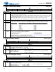
0 ADC1_
NG_ALL
ADC1 noise-gate ganging. Configures Channel A and B noise gating as independent (see ADC1x_NG) or ganged.
0 (Default) Independent noise gating on Channels A and B
1 Ganged noise gating on Channels A and B. Noise gate muting is applied to both channels when the signal amplitude of
both channels remains below the noise gate AB minimum threshold (refer to ADC1_NG_THRESH on p. 54) for longer
than the attack delay (debounce) time (refer to ADC1_NG_DELAY on p. 54).
• Noise gate muting is removed (released) without debouncing when the signal level exceeds the threshold.
• Noise gate attack and release rates (soft-ramped as a function of Fs or abrupt) are set according to DIGSFT on p. 50.
Bits Name Description