
User Manual


52 DS992F1
CS53L30
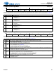
7.19 Input Bias Control 1
4 MUTE_ASP_
SDOUT1_PDN
Power down ASP_SDOUT1 when MUTE pin is asserted. Setting is ignored in TDM Mode.
0 (Default) Not affected by MUTE pin.
1 Powered down when MUTE pin asserted.
3, 2,
1, 0
MUTE_ADCxy_PDN Individual power down controls for the ADCs when the MUTE pin is asserted.
0 (Default) Not affected by MUTE pin
1 Powered down when MUTE pin asserted
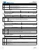
7.19 Input Bias Control 1
Address 0x21
R/W
76543210
IN4M_BIAS[1:0] IN4P_BIAS[1:0] IN3M_BIAS[1:0] IN3P_BIAS[1:0]
Default10101010
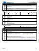
7.20 Input Bias Control 2
Address 0x22
R/W
76543210
IN2M_BIAS[1:0] IN2P_BIAS[1:0] IN1M_BIAS[1:0] IN1P_BIAS[1:0]
Default10101010
Bits Name Description
7:6,
5:4,
3:2,
1:0
INxy_BIAS Input xy pin bias control. Controls the input pin bias configuration.
00 Open. Set if no pin bias is desired. The pin is always unbiased in this state.
01 Weakly pulled down. Set if an internal weak pulldown is desired on the input pin.
10 (Default) Weak VCM. Set if weak VCM is desired, biased to weak VCM when necessary.
11 Reserved
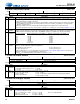
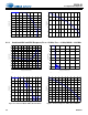
7.21 DMIC1 Stereo Control
Address 0x23
R/W
76 5 43210
— DMIC1_STEREO_ENB —
Default10 1 01000
7.22 DMIC2 Stereo Control
Address 0x24
R/W
76 5 43210
— DMIC2_STEREO_ENB —
Default11 1 01100
Bits Name Description
7:6 — Reserved
5DMICx_
STEREO_
ENB
DMIC2 stereo/mono enable.
0 Stereo input from the digital mic DMIC2_SD pin is enabled.
1 (Default) Mono (left-channel or rising-edge data) from DMIC2 is enabled and stereo is disabled.
4:0 — Reserved
7.23 ADC1/DMIC1 Control 1
Address 0x25
R/W
76 5432 1 0
ADC1B_PDN ADC1A_PDN — DMIC1_PDN DMIC1_SCLK_DIV CH_TYPE
Default 0 0 0 0 0 1 0 0
Bits Name Description
7, 6 ADC1x_
PDN
ADC1x power down. Configures the ADC Channel x power state. All analog front-end circuity (preamp, PGA, etc.) associated
with that channel is powered up or down accordingly. Also enables the digital decimator associated with that channel and must
be cleared if the input channel type is digital.
0 (Default) Powered up
1 Powered down
5:3 — Reserved
2DMIC1_
PDN
Power down digital mic clock. Determines the power state of the digital mic interface clock.
0 Powered up
1 (Default) Powered down.
Bits Name Description