
User Manual


34 DS992F1
CS53L30
4.9 Multichip Synchronization Protocol
4.9 Multichip Synchronization Protocol
Due to the multidrop capability of the CS53L30 TDM bus, it is conceivable to employ up to four CS53L30 chips to allow
up to 16 channels of audio capture. Extra care and sequencing steps have to be taken to ensure that the multichip
configuration meets the channel-to-channel phase matching specification across chips when using multiple CS53L30
chips in a system. Below is the recommended sequence to minimize phase mismatch across channels/chips. Any
deviation from this procedure causes deterministic, as well as nondeterministic, phase differences across chips and the
channel-to-channel phase mismatch specifications in Table 3-5 cannot be guaranteed. The SYNC pins of all devices must
be connected directly at the board level.
Synchronization sequence:
1. Release RESET
to all devices.
2. Configure the control port of all devices.
3. Clear PDN_ULP and/or PDN_LP in all devices.
4. Set the SYNC_EN bit of one of the devices only (the “initiator” device).
5. After successful synchronization, the SYNC_DONE status bit (see p. 57) is set on all connected CS53L30s that
have received the SYNC protocol (including the initiator device).
Alternate synchronization sequence:
1. Release RESET
to all devices.
2. Configure the control port of all devices.
3. Set the SYNC_EN bit of one of the devices only (the “initiator” device).
4. Clear PDN_ULP and/or PDN_LP in all devices except the initiator device.
5. Clear PDN_ULP and/or PDN_LP in the initiator device.
6. After successful synchronization, the SYNC_DONE status bit (see p. 57) is set on all connected CS53L30s that
have received the SYNC protocol (including the initiator device).
4.10 Input Path Source Selection and Powering
Table 4-5 describes how the CH_TYPE, ADCxy_PDN, and DMICx_PDN controls affect the CS53L30. The DMICx_PDN
control only affects the state of the digital mic interface clock.
4.11 Thermal Overload Notification
The CS53L30 can be configured to notify the system processor that its die temperature is too high. The processor can use
this notification to prevent damage to the CS53L30 and to other devices in the system. When notified, the processor should
react by powering down CS53L30 (and/or other devices in the system) partially or entirely, depending on the extent to
which the CS53L30’s power dissipation is the cause of its excessive die temperature. The CS53L30 is a low-power device
and any thermal overload is likely coming from elsewhere in the system.
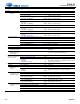
Table 4-5. ADCx/DMICx Input Path Source Select and Digital Power States (Where x = 1 or 2)
Control Register States Channel A Input Path Channel B Input Path
DMICx_SCLK
CH_TYPE DMICx_PDN ADCxA_PDN ADCxB_PDN Data Source Power State Data Source Power State
1000DMICxOnDMICxOnOn
1001DMICxOn—OffOn
1010—OffDMICxOnOn
1011—Off—OffOn
0100ADCxAOnADCxBOnOff
0101ADCxAOn—OffOff
0110—OffADCxBOnOff
0111—Off—OffOff