
User Manual


30 DS992F1
CS53L30
4.7 TDM Mode
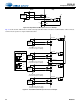
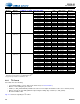
Figure 4-13. TDM Format—ASP_SCLK_INV = 0, SHIFT_LEFT = 1
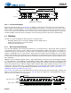
Figure 4-14. TDM Format—SCLK_INV = 1, SHIFT_LEFT = 0
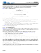
Figure 4-15. TDM Format—SCLK_INV = 1, SHIFT_LEFT = 1
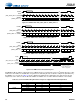
Figure 4-16. TDM Format—Unused SCLK Cycles
In TDM Master Mode, SCLK is a buffered version of MCLK and is not scaled to FS
ext
as it is in I
2
S Mode. Because of this,
and because the number of available bits on a given bus is defined by the ratio of SCLK to sample rate (SCLK/f
FSYNC
),
the TDM bus use can vary. As Table 4-3 shows, applying the SCLK/f
FSYNC
relationship to the supported clocks and
sample rates of the device results in different numbers of available slots as well as different numbers of unused bits.
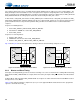
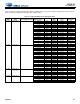
Table 4-3. Slot Count and Resulting Unused Clock Cycles for Supported SCLK and Sample Rates
SCLK Frequency [MHz] FSYNC Sample Rate [kHz] Number of Available Slots Resulting Number of Unused SCLK Cycles
5.6448 11.025 48 128
22.050 32 0
44.100 16 0
11.2896 11.025 48 640
22.050 48 128
44.100 32 0
0:7 0:6 0:5 0:4 0:3 0:2 0:1 0:0 1:7 1:6 1:5 m:2 m:1 m:0 0:7
FSYNC
SCLK
(ASP_SCLK_INV = 0, default)
SDOUT
(SHIFT_LEFT = 1)
Slot 0 Slot 1
m:0
Slot m
0:7 0:6 0:5 0:4 0:3 0:2 0:1 0:0 1:7 1:6 1:5 m:2 m:1 m:0 0:7
FSYNC
SCLK
(ASP_SCLK_INV = 1)
SDOUT
(SHIFT_LEFT = 0, default)
Slot 0 Slot 1
m:0
Slot m
0:7 0:6 0:5 0:4 0:3 0:2 0:1 0:0 1:7 1:6 1:5 m:2 m:1 m:0 0:7
FSYNC
SCLK
(ASP_SCLK_INV = 1)
SDOUT
(SHIFT_LEFT = 1)
Slot 0
Slot 1
m:0
Slot m
0:70:7 0:6 0:5 0:4 0:3 0:2 0:1 0:0 1:7 1:6 1:5 m:2 m:1 m:0
FSYNC
SCLK
(ASP_SCLK_INV = 0, default)
SDOUT
(SHIFT_LEFT = 0, default)
Slot 0 Slot 1
m:0
Slot m
Unused clocks
In Master Mode, all unused
SCLKs are driven.
In Slave Mode, bursted
SCLK is supported.