
User Manual


DS992F1 21
CS53L30
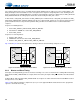
4.4 Capture-Path Inputs
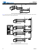
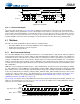
Fig. 4-4 shows details of the various analog input gain settings, including control register fields.
Figure 4-4. Input Gain Paths
4.4.1 Analog Input Configurations
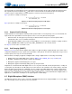
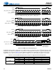
The CS53L30 implements fully differential analog input stages, as shown in Fig. 4-5. In addition to accepting fully
differential input signals, the inputs can be used in a pseudodifferential configuration to improve common mode noise
rejection with single-ended signals. In this configuration, a low-level reference signal is sensed at the ground point of the
internal mic or external mic jack and used as a pseudodifferential reference for the internal input amplifiers. Sitting between
the preamp and the PGA is an internal antialias filter with a first-order pole at 95 kHz and a first-order pole at 285 kHz.
Figure 4-5. Op-Amp Level Schematic—Analog Inputs
Fig. 4-6 shows the INx interface and the related connections recommended for a fully differential internal mic. These
connections are truncated in Fig. 4-6.
–6 to +12 dB
with 0.5-dB
steps
Bypass, +10,
or +20 dB
0 or +20 dB
and/or
–96 to +12 dB
with 1-dB steps or
– dB (mute)
INx±,
(x=1,2)
Gain Adjust
Digital Gain
Adjust
ADC1xPGA
...
(Note 1)
(Note 1)
Bypass, +10,
or +20 dB
INx±,
(x=3,4)
Gain AdjustDigital Gain
Adjust
ADC2xPGA
...
(Note 1)
(Note 1)
1. Gains within analog blocks vary with supply voltage, with temperature, and from part to part. The gain values listed for these blocks
are typical values with nominal parts and conditions.
ADC1x_PREAMP
on p. 54
ADC1x_DIG_BOOST on p. 53
ADC1x_VOL on p. 54
ADC2x_PGA_VOL
on p. 56
ADC2x_PREAMP
on p. 56
ADC1x_PGA_VOL
on p. 54
ADC2x_DIG_BOOST on p. 55
ADC2x_VOL on p. 56
+
–
Preamp+
+
–
Preamp–
INx–
INx+
100 k
900 k
900 k
100 k
Quick-
Ref
700 k 700 k
VA
Weak-VCM
700 k 700 k
Weak-VCM
VA
VCM
+
–
PGA
ADCx+
ADCx–
ADC1x_PGA_VOL
ADC2x_PGA_VOL
ADC1x_PREAMP
ADC2x_PREAMP