
Manual


CS5378
DS639F3 44
13.FIR FILTER
The finite impulse response (FIR) filter block consists of two cascaded stages, FIR1 and FIR2. It compen-
sates for SINC filter droop and creates a low-pass corner to block aliased components of the input signal.
On-chip linear phase or minimum phase coefficients can be selected using a configuration command, or
the coefficients can be programmed for a custom filter response.
13.1 FIR1 Filter
The FIR1 filter stage has a decimate by four architecture. It compensates for SINC filter droop and flattens
the magnitude response of the pass band.
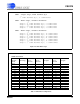
The on-chip linear and minimum phase coefficient sets are 48-tap, with a maximum 255 programmable
coefficients. All coefficients are normalized to 24-bit two’s complement full scale, 0x7FFFFF.
The characteristic equation for FIR1 is a convolution of the input values, X(n), and the filter coefficients,
h(k), to produce an output value, Y.
Y = [h(k)*X(n-k)] + [h(k+1)*X(n-(k+1))] + ...
13.2 FIR2 Filter
The FIR2 filter stage has a decimate by two architecture. It creates a low-pass brick wall filter to block
aliased components of the input signal.
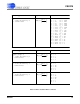
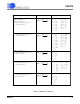
The on-chip linear and minimum phase coefficient sets are 126-tap, with a maximum 255 programmable
coefficients. All coefficients are normalized to 24-bit two’s complement full scale, 0x7FFFFF.
The characteristic equation for FIR2 is a convolution of the input values, X(n), and the filter coefficients,
h(k), to produce an output value, Y.
Y = [h(k)*X(n-k)] + [h(k+1)*X(n-(k+1))] + ...
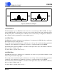
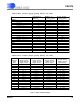
FIR1 Filter - decimate by 4 FIR2 Filter - decimate by 2
Figure 25. FIR Filter Block Diagram