
Manual


CS5378
DS639F3 11
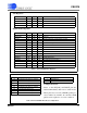
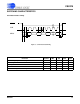
SPI Registers
Digital Filter Registers
Name Addr. Type # Bits Description
SPICTRL 00 - 02 R/W 8, 8, 8 SPI Control
SPICMD 03 - 05 R/W 8, 8, 8 SPI Command
SPIDAT1 06 - 08 R/W 8, 8, 8 SPI Data 1
SPIDAT2 09 - 0B R/W 8, 8, 8 SPI Data 2
Name Addr. Type # Bits Description
CONFIG 00 R/W 24 Hardware Configuration
RESERVED 01-0D R/W 24 Reserved
GPCFG 0E R/W 24 GPIO[7:0] Direction, Pull-up Enable, and Data
RESERVED 0F-1F R/W 24 Reserved
FILTCFG 20 R/W 24 Digital Filter Configuration
GAIN 21 R/W 24 Gain Correction
RESERVED 22-24 R/W 24 Reserved
OFFSET 25 R/W 24 Offset Correction
RESERVED 26-28 R/W 24 Reserved
TIMEBRK 29 R/W 24 Time Break Delay
TBSCFG 2A R/W 24 Test Bit Stream Configuration
TBSGAIN 2B R/W 24 Test Bit Stream Gain
SYSTEM1 2C R/W 24 User Defined System Register 1
SYSTEM2 2D R/W 24 User Defined System Register 2
VERSION 2E R/W 24 Hardware Version ID
SELFTEST 2F R/W 24 Self-Test Result Code
Table 3. SPI and Digital Filter Registers
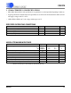
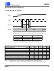
Table 4. PLL and BOOT Mode Reset Configurations
PLL[2:0] Mode Selection on Reset
111 32.768 MHz clock input (PLL bypass).
110 1.024 MHz clock input.
101 2.048 MHz clock input.
100 4.096 MHz clock input.
011 32.768 MHz clock input (PLL bypass).
010 1.024 MHz Manchester input.
001 2.048 MHz Manchester input.
000 4.096 MHz Manchester input.
Configuration Note:
States of the PLL[2:0] and BOOT pins are
latched immediately after reset to select modes.
These pins have a weak (~100 kΩ) pull-up re-
sistor enabled by default. An external 10 kΩ
pull-down is required to set a low condition.
BOOT Mode Selection on Reset
1 EEPROM boot
0 Microcontroller boot