
User guide


CS5376A
76 DS612F4
21.2.1 JTAG Reset
As required by the IEEE 1149.1 specification, the
JTAG TRST
signal is independent of the CS5376A
RESET
signal. In systems not using the JTAG port,
TRST
should be connected to ground. In systems
using the JTAG port, TRST
and RESET should be
independently driven to provide reset capability
during boundry scan.
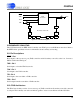
21.2.2 TAP Controller
The test access port (TAP) controller manages
commands and data through the boundary scan
chain. It supports the four JTAG instructions and
contains the IDCODE listed in Table 20.
The TAP controller also implements the 16 JTAG
state assignments from the IEEE 1149.1 specifica-
tion, which are sequenced using TMS and TCK.
21.2.3 Boundary Scan Cells
The CS5376A JTAG test port provides access to all
device pins via internal boundary scan cells. When
the JTAG port is disabled, boundary scan cells are
transparent and do not affect CS5376A operation.
When the JTAG port is enabled, boundary scan
cells can write and read each pin independent of
CS5376A operation.
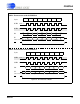
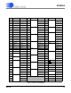
Boundary scan cells are serially linked to create a
scan chain around the CS5376A controlled by the
TAP controller. Table 21 lists the scan cell map-
ping of the CS5376A.
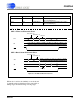
JTAG Instructions Encoding
BYPASS 11
EXTEST 00
IDCODE 01
SAMPLE / PRELOAD 10
JTAG IDCODE
Components
Encoding
Revision 0x10000000
Device ID 0x05376000
Manufacturer ID 0x000000C9
CS5376A IDCODE 0x153760C9
Table 20. JTAG Instructions and IDCODE