
User guide


CS5376A
DS612F4 73
SPI modes 1 and 4 work similarly to modes 0 and
3, with the serial clock defined to have data valid on
falling edges and transitioning on rising edges.
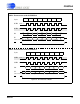
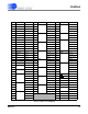
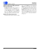
Figure 38. SPI 2 Master Mode Transactions
SO
0x02 ADDR Data1
SI
SO
SI
SPI 2 Write to External Slave
SPI 2 Read from External Slave
Data3
Data2
0x03 ADDR
Data1 Data3Data2
CS
CS
SPI2CMD[15:8]
SPI2CMD[7:0]
SPI2DAT
SPI2CMD[15:8]
SPI2CMD[7:0]
SPI2DAT
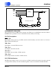
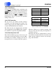
Instruction Opcode Address Definition
Write 0x02 SPI2CMD[7:0] Write serial peripheral beginning at the address
given in SPI2CMD[7:0].
Read 0x03 SPI2CMD[7:0] Read serial peripheral beginning at the address
given in SPI2CMD[7:0].