
User guide

CS5376A
DS612F4 7
1. GENERAL DESCRIPTION
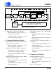
The CS5376A is a multi-channel digital filter with
integrated system peripherals. Figure 1 illustrates a
simplified block diagram of the CS5376A.
1.1 Digital Filter Features
• Multi-channel decimation filter for
CS5371A/72A ∆Σ modulators.
- 1, 2, 3, or 4 channel concurrent operation.
• Synchronous operation for simultaneous sam-
pling in multi-sensor systems.
- Internal synchronization of digital filter
phase to an external SYNC signal.
• Multiple output word rates, including low
bandwidth rates.
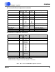
- Standard output rates: 4000, 2000, 1000,
500, 333, 250 SPS.
- Low bandwidth rates: 200, 125, 100, 50, 40,
25, 20, 10, 5, 1 SPS.
• Flexible digital filter configuration. (See Figure
2)
- Cascaded SINC, FIR, and IIR filters with
selectable output stage.
- Linear and minimum phase FIR low-pass
filter coefficients included.
- 3 Hz Butterworth IIR high-pass filter coef-
ficients included.
- FIR and IIR coefficients are programmable
to create a custom filter response.
• Digital gain correction.
- Individual channel gain correction to nor-
malize signal amplitudes.
Figure 1. CS5376A Block Diagram
SCK1
Serial Data Output Port
Decimation and
Filtering Engine
Modulator Data
Interface
Test Bit Stream Controller
Clock and
Synchronization
TBSCLK
TBSDATA
SPI 1
Serial Peripheral Interface 1
JTAG
Interface
Time Break Controller
SPI 2
Serial Peripheral Interface 2
GPIO
General Purpose I/O
SDCLK
SDDAT
SDTKI
BOOT
VD (x2)
VDD1
VDD2 (x2)
SYNC
CLK
MCLK
MSYNC
TIMEB
MISO
MOSI
SSI
SINT
SDRDY
SCK2
SO
SI1
SI2
SI3
SI4
GPIO11:EECS
GPIO10
GPIO9
GPIO8
GPIO7
GPIO6
GPIO5
GPIO4:CS4
GPIO3:CS3
GPIO2:CS2
GPIO1:CS1
GPIO0:CS0
GND (x2)
GND2 (x2)
GND1
MDATA [4:1]
MFLAG [4:1]
TCK
TMS
TDI
TDO
RESET
TRST