
User guide


CS5376A
DS612F4 23
5. RESET CONTROL
The CS5376A reset signal is active low. When re-
leased, a series of self-tests are performed and the
device either actively boots from an external EE-
PROM or enters an idle state waiting for microcon-
troller configuration.
5.1 Pin Descriptions
RESET - Pin 55
Reset input, active low.
BOOT - Pin 56
Boot mode select, latched following a RESET ris-
ing edge.
BOOT = 1 = EEPROM boot
BOOT = 0 = Microcontroller boot
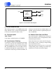
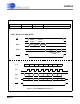
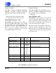
5.2 Reset Self-Tests
After RESET is released but before booting, a se-
ries of digital filter self-tests are run. Results are
combined into the SELFTEST register (0x2F),
with 0x0AAAAA indicating all passed. Self-tests
require 60 ms to complete, after which configura-
tion commands are serviced.
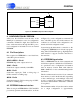
5.3 Boot Configurations
The logic state of the BOOT pin after reset deter-
mines if the CS5376A actively reads configuration
information from EEPROM or enters an idle state
waiting for a microcontroller to write configuration
commands.
EEPROM Boot
When the BOOT pin is high after reset, the
CS5376A actively reads data from an external seri-
al EEPROM and then begins operation in the spec-
ified configuration. Configuration commands and
data are encoded in the EEPROM as specified in
the ‘Configuration By EEPROM’ section of this
data sheet, starting on page 26.
Microcontroller Boot
When the BOOT pin is low after reset, the
CS5376A enters an idle state waiting for a micro-
controller to write configuration commands and
initialize filter operation. Configuration commands
and data are written as specified in the ‘Configura-
tion By Microcontroller’ section of this data sheet,
starting on page 32.
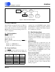
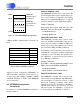
RESET
Self-Tests
SELFTEST
Register
BOOT
Pin
EEPROM
Boot
µController
Boot
1
0
Figure 11. Reset Control Block Diagram
Self-Test
Type
Pass
Code
Fail
Code
Program ROM 0x00000A 0x00000F
Data ROM 0x0000A0 0x0000F0
Program RAM 0x000A00 0x000F00
Data RAM 0x00A000 0x00F000
Execution Unit 0x0A0000 0x0F0000