
Instruction Manual

CS5374
CS5374
6
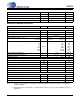
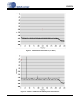
ANALOG CHARACTERISTICS (CONT.)
Notes: 9. The upper bandwidth limit is determined by the selected digital filter cut-off frequency.
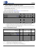
10. Anti-alias capacitors are discrete external components and must be of good quality (C0G, NPO, poly).
Poor-quality capacitors will degrade total harmonic distortion (THD) performance. See Figure 1 for
external anti-alias filter connections.
11. Maximum integrated noise over the measurement bandwidth for the voltage reference device attached
to the VREF inputs.
Parameter Symbol Min Typ Max Unit
Modulator Inputs
Input Signal Frequencies (Note 9) V
BW
DC - 2000 Hz
Full-scale Differential AC Input V
AC
--5V
pp
Full-scale Differential DC Input V
DC
-2.5 - 2.5 V
DC
Input Common Mode Voltage V
CM
-
(VA-)+2.5
-V
Input Voltage Range (V
cm
±Signal) V
RNG
(VA-)+0.7
-
(VA+)-1.25
V
Differential Input Impedance INR±
INF±
ZDIF
INR
ZDIF
INF
-
-
20
1
-
-
kΩ
MΩ
Single-ended Input Impedance INR±
INF±
ZSE
INR
ZSE
INF
-
-
40
2
-
-
kΩ
MΩ
External Anti-alias Filter Series Resistance
(Note 10) Differential Capacitance
R
AA
C
DIFF
-
-
680
20
-
-
Ω
nF
VREF Inputs
[VREF+] - [VREF-] (Note 2, 3) VREF - 2.500 - V
VREF- (Note 4)VREF- - VA- - V
VREF Input Current VREF
II
-120- µA
VREF Input Noise (Note 11)VREF
IN
--1µV
rms
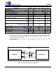
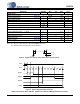
MODULATOR
INR+
INF+
INF-
INR-
20nF
C0G
20nF
C0G
680
AMPLIFIER
OUT+
OUT-
680
680
680
CS5374
Figure 1. External Anti-alias Filter Components