
Instruction Manual

CS5374
CS5374
41
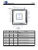
Differential Amplifier Analog Outputs
OUT1–,
OUT1+
46
47
O
Channel 1 differential analog output.
GUARD1 48 O
Guard output voltage for analog input Channel 1.
GUARD2 13 O
Guard output voltage for analog input Channel 2.
OUT2+,
OUT2–
14
15
O
Channel 2 differential analog output.
Modulator Analog Inputs
INR1+,
INF1+,
INF1–,
INR1–
42
43
44
45
I
Channel 1 analog differential rough and fine inputs.
From the Channel 1 differential anti-alias filter.
INR2–,
INF2–,
INF2+,
INR2+
16
17
18
19
I
Channel 2 analog differential rough and fine inputs.
From the Channel 2 differential anti-alias filter.
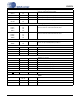
Voltage Reference
VREF+,
VREF–
21
22
I
Voltage reference input.
Refer to the Specified Operating Conditions.
Serial Interface
CS 25 I
Chip select. Active low.
SCLK 26 I
Serial clock.
SDI 27 I
Serial data in to device.
SDO 28 O
Serial data out of device.
Modulator Interface
MCLK 36 I
Modulator clock input.
MSYNC 35 I
Modulator sync input.
MFLAG1 33 O
Channel 1 modulator flag output.
MDATA1 34 O
Channel 1 modulator data output.
MFLAG2 29 O
Channel 2 modulator flag output.
MDATA2 30 O
Channel 2 modulator data output.
Device Reset
RST 37 I
Reset. Active low.
Other
NC 20, 23, 24,
38, 41
---
No connect.
DNC 5, 8 ---
Do Not Connect.
Thermal Pad 49 I
Connect to VA–. Do not connect to GND.