
Instruction Manual


CS5374
CS5374
39
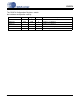
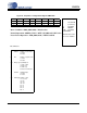
(MSB)7654321(LSB)0
adc_lpwr --- amp_i1_1 amp_i1_0 rough i1_tail amp_i5_1 amp_i5_0
R/W R/W R/W R/W R/W R/W R/W R/W
00000000
Figure 24. Power Configuration Register PWRCFG
Bit definitions:
7 adc_lpwr Modulator Bias
1: reduced current
0: nominal current
6 --- reserved
5:4 amp_i1 Amplifier i1 Bias
11: 2/3
10: 1/3
01: 4/3
00: nominal current
3 rough Modulator Rough Phase
1: reduced current
0: nominal current
2 i1_tail Amplifier i1 Tail Current
1: reduced current
0: nominal current
1:0 amp_i5 Amplifier i5 Bias
11: 7/11
10: 9/13
01: 15/13
00: nominal current
Address: 0x04
--- Not defined
(read as 0)
R Readable
WWritable
R/W Readable
and Writable
Bits in bottom rows
are reset condition.
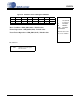
Reset Condition : 0000_0000 (0x00) : Default value
Normal Operation : 1000_1111 (0x8F) : Reduced power
Power Down Operation : 0000_0000 (0x00) : Default value