
Instruction Manual

Copyright Cirrus Logic, Inc. 2010
(All Rights Reserved)
Preliminary Product Information
This document contains information for a new product.
Cirrus Logic reserves the right to modify this product without notice.
http://www.cirrus.com
Dual High-performance Amplifier &
ΔΣ
Modulator
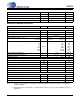
Features
High Input Impedance Differential Amplifier
• Ultra-low input bias: < 1 pA
• Max signal amplitude: 5 Vpp differential
Fourth Order Delta-Sigma (ΔΣ) Modulator
• Signal Bandwidth: DC to 2 kHz
• Common mode rejection: 110 dB CMRR
Differential Analog Input, Digital ΔΣ Output
• Multiplexed inputs: INA, INB, 800Ω termination
• Selectable Gain: 1x, 2x, 4x, 8x, 16x, 32x, 64x
Excellent Amplifier Noise Performance
•1.5 μVpp between 0.1 Hz and 10 Hz
• 11 nV /
√Hz from 200 Hz to 2 kHz
High Modulator Dynamic Range
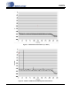
• 126 dB SNR @ 215 Hz BW (2 ms sampling)
• 123 dB SNR @ 430 Hz BW (1 ms sampling)
Low Total Harmonic Distortion
• –118 dB THD typical (0.000126%)
• –108 dB THD maximum (0.0004%)
Low Power Consumption
• Normal operation: 6.5 mA per channel
• Power down: 15 μA per channel max
Dual Power Supply Configuration
• VA+ = +2.5 V; VA– = –2.5 V; VD = +3.3 V
Description
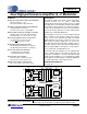
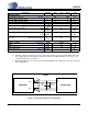
The CS5374 combines two marine seismic analog mea-
surement channels into one 7 mm x 7 mm QFN
package. Each measurement channel consists of a high
input impedance programmable gain differential amplifi-
er that buffers analog signals into a high-performance,
fourth-order ΔΣ modulator. The low-noise ΔΣ modulator
converts the analog signal into a one-bit serial bit stream
suitable for the CS5376A digital filter.
Each amplifier has two sets of external inputs, INA and
INB, to simplify system design as inputs from a hydro-
phone sensor or the CS4373A test DAC. An internal
800Ω termination can also be selected for noise tests.
Gain settings are binary weighted (1x, 2x, 4x, 8x, 16x,
32x, 64x) and match the CS4373A test DAC output at-
tenuation settings for full-scale testing at all gain ranges.
Both the input multiplexer and gain are set by registers
accessed through a standard SPI™ port.
Each fourth-order ΔΣ modulator has very high dynamic
range combined with low total harmonic distortion and
low power consumption. It converts differential analog
signals from the amplifier to an oversampled ΔΣ serial bit
stream which is decimated by the CS5376A digital filter
to a 24-bit output at the final output word rate.
ORDERING INFORMATION
See page 43.
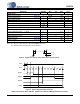
INA1+
INB1+
MUX1
MUX2
INB1-
INA1-
GUARD1
+
-
-
+
400 Ω 400 Ω
INA2+
INB2+
INB2-
INA2-
+
-
-
+
400 Ω 400 Ω
Reset, Clock,
and
Synchronization
INR1- VA+
MFLAG1
MCLK
MSYNC
MFLAG2
MDATA2
GAIN1GAIN2
GUARD2 INR2- INR2+
4
th
Order
Modulator
4
th
Order
Modulator
INF1- INF1+INR1+
RST
SPI
TM
Serial
Interface
SDI
SDO
SCLK
CS
INF2+INF2-OUT2-OUT2+
OUT1+ OUT1-
CS5374
VA-
GND
VD
VREF-VREF+
VA+
VA-
MDATA1
SEP '10
DS862F2
CS5374