
Manual

CS5371 CS5372
16 DS255F3
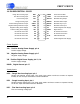
10. PIN DESCRIPTION - CS5371
Power Supplies
VA+
_
Positive Analog Power Supply, pin 8
Positive supply voltage.
VA-
_
Negative Analog Power Supply, pin 7
Negative supply voltage.
VD
_
Positive Digital Power Supply, pin 13, 18
Positive supply voltage.
DGND
_
Digital Ground, pin 17
Analog Inputs
INR+
_
Rough Non-Inverting Input, pin 1
Rough non-inverting analog input. The rough input settles non-linear currents to improve
linearity on the fine input and reduce harmonic distortion.
INR-
_
Rough Inverting Input, pin 4
Rough inverting analog input. The rough input settles non-linear currents to improve linearity
on the fine input and reduce harmonic distortion.
INF+
_
Fine Non-Inverting Input, pin 2
Fine non-inverting analog input.
1
2
3
4
5
6
7
817
18
19
20
21
22
23
24
9
10
11
12 13
14
15
16
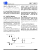
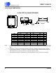
Rough Non-Inverting Input INR+
Fine Non-Inverting Input INF+
Fine Inverting Input INF-
Rough Inverting Input INR-
Positive Voltage Reference Input VREF+
Negative Voltage Reference Input VREF-
Negative Analog Power Supply VA-
Positive Analog Power Supply VA+
No Internal Connection NC
No Internal Connection NC
No Internal Connection NC
No Internal Connection NC
PWDN Power-down Enable
LPWR Low Power Mode Select
MFLAG Modulator Flag Output
MDATA Modulator Data Output
MSYNC Modulator Sync Input
MCLK Modulator Clock Input
VD Positive Digital Power Supply
DGND Digital Ground
NC No Internal Connection
NC No Internal Connection
OFST Offset Mode Select
VD Positive Digital Power Supply