
User Manual


34 DS625F5
CS5364
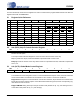
5.6 04h (HPF) High-Pass Filter Register
Default: 0x00, all high-pass filters enabled.
The High-Pass Filter Register is used to enable or disable a high-pass filter that exists for each channel.
These filters are used to perform DC offset calibration, a procedure that is detailed in “DC Offset Control”
on page 29.
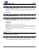
5.7 05h Reserved
5.8 06h (PDN) Power Down Register
Default: 0x00 - everything powered up
The Power Down Register is used as needed to reduce the chip’s power consumption.
Bit[7] RESERVED
Bit[6] RESERVED
Bit[5] PDN-BG When set, this bit powers-down the bandgap reference.
Bit[4] PDN-OSC controls power to the internal oscillator core. When asserted, the internal oscillator core is
shut down, and no clock is supplied to the chip. If the chip is running off an externally supplied clock at the
MCLK pin, it is also prevented from clocking the device internally.
Bit[1:0] PDN When any bit is set, all clocks going to a channel pair are turned off, and the serial data outputs
are forced to all zeroes.
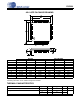
5.9 07h Reserved
5.10 08h (MUTE) Mute Control Register
Default: 0x00, no channels are muted.
The Mute Control Register is used to mute or unmute the serial audio data output of individual channels.
When a bit is set, that channel’s serial data is muted by forcing the output to all zeroes.
R/W76543210
R/W RESERVED RESERVED RESERVED RESERVED HPF4
HPF3 HPF2 HPF1
R/W76543210
RESERVED - - - - - - - -
R/W76543210
R/W RESERVED PDN-BG PDN-OSC RESERVED RESERVED PDN43 PDN21
R/W76543210
RESERVED - - - - - - - -
R/W76543210
R/W RESERVED RESERVED RESERVED RESERVED MUTE4 MUTE3 MUTE2 MUTE1