
User Manual


DS625F5 25
CS5364
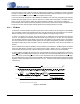
4.7 Master and Slave Clock Frequencies
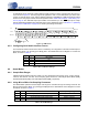
Tables 4 through 12 show the clock speeds for sample rates of 48 kHz, 96 kHz and 192 kHz. The MC-
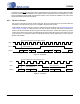
LK/LRCK ratio should be kept at a constant value during each mode. In Master Mode, the device outputs
the frequencies shown. In Slave Mode, the SCLK/LRCK ratio can be set according to design preference.
However, device performance is guaranteed only when using the ratios shown in the tables.
Table 4. Frequencies for 48 kHz Sample Rate using LJ/I²S
Table 5. Frequencies for 96 kHz Sample Rate using LJ/I²S
Table 6. Frequencies for 192 kHz Sample Rate using LJ/I²S
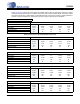
Table 7. Frequencies for 48 kHz Sample Rate using TDM
Table 8. Frequencies for 48 kHz Sample Rate using TDM
Control Port Mode only
LJ/I²S MASTER OR SLAVE SSM Fs = 48 kHz
MCLK Divider 4 3 2 1.5 1
MCLK (MHz)
49.152 36.864 24.576 18.384 12.288
SCLK (MHz)
3.072 3.072 3.072 3.072 3.072
MCLK/LRCK Ratio 1024 768 512 384 256
SCLK/LRCK Ratio
64 64 64 64 64
LJ/I²S MASTER OR SLAVE DSM Fs = 96 kHz
MCLK Divider 4 3 2 1.5 1
MCLK (MHz) 49.152 36.864 24.567 18.384 12.288
SCLK (MHz)
6.144 6.144 6.144 6.144 6.144
MCLK/LRCK Ratio
512 384 256 192 128
SCLK/LRCK Ratio 64 64 64 64 64
LJ/I²S MASTER OR SLAVE QSM Fs = 192 kHz
MCLK Divider 4 3 2 1.5 1
MCLK (MHz) 49.152 36.864 24 18.384 12.288
SCLK (MHz)
12.288 12.288 12.288 12.288 12.288
MCLK/LRCK Ratio
256 192 128 96 64
SCLK/LRCK Ratio 64 64 64 64 64
TDM MASTER SSM Fs = 48 kHz
MCLK Divider 4 3 2 1.5 1
MCLK (MHz) 49.152 36.864 24.567 18.384 12.288
SCLK (MHz)
12.288 12.288 12.288 12.288 12.288
MCLK/FS Ratio
1024 768 512 384 256
SCLK/FS Ratio 256 256 256 256 256
TDM SLAVE SSM Fs = 48 kHz
MCLK Divider 4 3 2 1.5 1
MCLK (MHz)
49.152 36.864 24.567 18.384 12.288
SCLK (MHz)
12.288 12.288 12.288 12.288 12.288
MCLK/FS Ratio 1024 768 512 384 256
SCLK/FS Ratio
256 256 256 256 256