
User Manual


24 DS625F5
CS5364
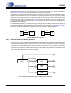
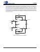
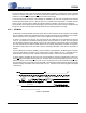
4.6.3 Master Mode Clock Dividers
Figure 13 shows the configuration of the MCLK dividers and the sample rate dividers for Master Mode, in-
cluding the significance of each MCLK divider pin (in Stand-Alone Mode) or bit (in Control Port Mode).
Figure 13. Master Mode Clock Dividers
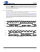
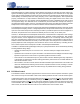
4.6.4 Slave Mode Audio Clocking With Auto-Detect
In Slave Mode, CS5364 auto-detects speed mode, which eliminates the need to configure M1 and M0 when
changing among speed modes. The external MCLK is subject to clock dividers as set by the clock divider
pins in Stand-Alone Mode or the clock divider bits in Control Port Mode. The CS5364 compares the divided-
down, internal MCLK to the incoming LRCK/FS and sets the speed mode based on the MCLK/LRCK ratio
as shown in Figure 14.
Figure 14. Slave Mode Auto-Detect Speed
÷ 128
÷ 64
M0M1
LRCK/ FS
Single
Speed
Quad
Speed
Double
Speed
00
01
10
÷ 2
÷ 4
÷ 1
SCLK
Single
Speed
Quad
Speed
Double
Speed
00
01
10
÷ 256
pin
CLKMODE
MDIV
n/a
MCLK
÷ 1
÷ 1.5 ÷ 2
÷ 1
÷ 2
÷ 1
bit MDIV1
MDIV0
0/1 0/1 0/1
MCLK DIVIDERS
SAMPLE RATE DIVIDERS
CLKMODE
128
64
Single-Speed
256
pin
CLKMODE
MDIV
n/a
External
MCLK
÷ 1
÷ 1.5 ÷ 2
÷ 1
÷ 2
÷ 1
bit MDIV1
MDIV0
0/1 0/1 0/1
MCLK DIVIDERS
CLKMODE
÷LRCK
LRCK
Double-Speed
Quad-Speed
SPEED MODE
Internal
MCLK