
User Manual


DS625F5 17
CS5364
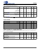
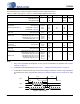
SWITCHING SPECIFICATIONS - CONTROL PORT - I²C TIMING
Inputs: Logic 0 = DGND, Logic 1 = VLC, SDA C
L
=30pF
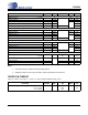
Notes:
1. Data must be held for sufficient time to bridge the transition time, t
fc
, of SCL.
Figure 5. I²C Timing
2. The operational timing specification deviates from the I2C-Bus Specification and User Manual of
250 ns.
Parameter Symbol Min Max Unit
SCL Clock Frequency f
scl
- 100 kHz
RST
Rising Edge to Start t
irs
600
-
ns
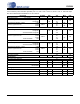
Bus Free Time Between Transmissions t
buf
4.7 µs
Start Condition Hold Time (prior to first clock pulse) t
hdst
4.0
µs
Clock Low time t
low
4.7
Clock High Time t
high
4.0
Setup Time for Repeated Start Condition t
sust
4.7
SDA Hold Time from SCL Falling (Note 1)
t
hdd
0
SDA Setup time to SCL Rising (Note 2) t
sud
600 ns
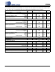
Rise Time of SCL and SDA t
rc
-1µs
Fall Time SCL and SDA t
fc
-300ns
Setup Time for Stop Condition t
susp
4.7 - µs
Acknowledge Delay from SCL Falling t
ack
300 1000 ns
t
buf
t
hdst
t
lo w
t
hdd
t
high
t
sud
Stop Start
SDA
SCL
t
irs
RST
t
hdst
t
rc
t
fc
t
sust
t
susp
Start
Stop
Repe ated
t
rd
t
fd
t
ack