
User Manual


10 DS625F5
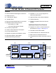
CS5364
3. CHARACTERISTICS AND SPECIFICATIONS
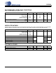
RECOMMENDED OPERATING CONDITIONS
GND = 0 V, all voltages with respect to 0 V.
1. TDM Quad-Speed Mode specified to operate correctly at VLS 3.14 V.
ABSOLUTE RATINGS
Operation beyond these limits may result in permanent damage to the device. Normal operation is not guaranteed
at these extremes. Transient currents up to ±100 mA on the analog input pins will not cause SCR latch-up.
SYSTEM CLOCKING
Parameter Symbol Min Typ Max Unit
DC Power Supplies: Positive Analog
Positive Crystal
Positive Digital
Positive Serial Logic
Positive Control Logic
VA
VX
VD
VLS
VLC
4.75
4.75
3.14
1.71
1
1.71
5.0
5.0
3.3
3.3
3.3
5.25 V
Ambient Operating Temperature (-CQZ)
(-DQZ)
T
AC
T
AA
-40
-40
-
-
85
105
°C
Parameter Symbol Min Typ Max Units
DC Power Supplies: Positive Analog
Positive Crystal
Positive Digital
Positive Serial Logic
Positive Control Logic
VA
VX
VD
VLS
VLC
-0.3 - +6.0 V
Input Current I
in
-10
-
10 mA
Analog Input Voltage V
IN
-0.3
VA+0.3
V
Digital Input Voltage V
IND
VL+0.3
Ambient Operating Temperature (Power Applied) T
A
-50 +125
C
Storage Temperature T
stg
-65 +150
Parameter Symbol Min Typ Max Unit
Input Master Clock Frequency MCLK 0.512 55.05 MHz
Input Master Clock Duty Cycle t
clkhl
40 60 %