
User Manual


DS565F2 17
CS5351
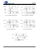
4.2.2 Master Mode
In Master Mode, LRCK and SCLK operate as outputs. The left/right and serial clocks are internally derived
from the master clock with the left/right clock equal to Fs and the serial clock equal to 64x Fs, as shown
in Figure 23. Refer to Table 3 for common master clock frequencies.
4.3 Power-Up Sequence
Reliable power-up can be accomplished by keeping the device in reset until the power supplies, clocks and
configuration pins are stable. It is also recommended that reset be enabled if the analog or digital supplies
drop below the minimum specified operating voltages to prevent power glitch related issues.
The internal reference voltage must be stable for the device to produce valid data. Therefore, there is a de-
lay between the release of reset and the generation of valid output due to the finite output impedance of
FILT+ and the presence of the external capacitance.
÷ 128
÷ 256
÷ 64
M0M1
LRCK Output
(Equal to Fs)
Single
Speed
Quad
Speed
Double
Speed
00
01
10
÷ 2
÷ 4
÷ 1
SCLK Output
Single
Speed
Quad
Speed
Double
Speed
00
01
10
÷ 2
÷ 1
0
1
MCLK
MDIV
Figure 23. CS5351 Master Mode Clocking
SAMPLE RATE (kHz)
MDIV = 0
MCLK (MHz)
MDIV = 1
MCLK (MHz)
32 8.192 16.384
44.1 11.2896 22.5792
48 12.288 24.576
64 8.192 16.384
88.2 11.2896 22.5792
96 12.288 24.576
176.4 11.2896 22.5792
192 12.288 24.576
Table 3. CS5351 Common Master Clock Frequencies