
Manual


32 DS861PP3
CS5346
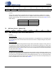
7.8.2 Analog Input Selection (Bits 2:0)
Function:
These bits are used to select the input source for the PGA and ADC. Please see Table 12.
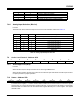
7.9 Active Level Control - Address 0Ch
7.9.1 Active High/ Low
(Bit 0)
Function:
When this bit is set, the INT pin functions as an active high CMOS driver.
When this bit is cleared, the INT pin functions as an active low open drain driver and will require an exter-
nal pull-up resistor for proper operation.
7.10 Status - Address 0Dh
For all bits in this register, a ‘1’ means the associated condition has occurred at least once since the register
was last read. A ‘0’ means the associated condition has NOT occurred since the last reading of the register.
Status bits that are masked off in the associated mask register will always be ‘0’ in this register. This register
defaults to 00h.
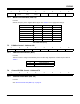
PGASoft PGAZeroCross Mode
0 0 Changes to affect immediately
0 1 Zero Cross enabled
1 0 Soft Ramp enabled
1 1 Soft Ramp and Zero Cross enabled (default)
Table 11. PGA Soft Cross or Zero Cross Mode Selection
Sel2 Sel1 Sel0 PGA/ADC Input
0 0 0 Microphone-Level Inputs (+32 dB Gain Enabled)
0 0 1 Line-Level Input Pair 1
0 1 0 Line-Level Input Pair 2
0 1 1 Line-Level Input Pair 3
1 0 0 Line-Level Input Pair 4
1 0 1 Line-Level Input Pair 5
1 1 0 Line-Level Input Pair 6
1 1 1 Reserved
Table 12. Analog Input Multiplexer Selection
76543210
Reserved Reserved Reserved Reserved Reserved Reserved Reserved Active_H/L
76543210
Reserved Reserved Reserved Reserved ClkErr Reserved Ovfl Undrfl