CS5345 104 dB, 24-Bit, 192 kHz Stereo Audio ADC A/D Features General Description Multi-Bit Delta Sigma Modulator The CS5345 integrates an analog multiplexer, programmable gain amplifier, and stereo audio analog-to-digital converter. The CS5345 performs stereo analog-to-digital (A/D) conversion of up to 24-bit serial values at sample rates up to 192 kHz. 104 dB Dynamic Range -95 dB THD+N Stereo 6:1 Input Multiplexer Programmable Gain Amplifier (PGA) – ± 12 dB Gain, 0.
CS5345 TABLE OF CONTENTS 1. PIN DESCRIPTIONS ......................................................................................................................... 5 2. CHARACTERISTICS AND SPECIFICATIONS ...................................................................................... 7 SPECIFIED OPERATING CONDITIONS ............................................................................................. 7 ABSOLUTE MAXIMUM RATINGS ................................................................
CS5345 6.6.1 Channel B PGA Gain (Bits 5:0) ............................................................................................. 34 6.7 Channel A PGA Control - Address 08h .......................................................................................... 35 6.7.1 Channel A PGA Gain (Bits 5:0) ............................................................................................. 35 6.8 ADC Input Control - Address 09h .....................................................................
CS5345 Table 5. Device Revision .......................................................................................................................... 32 Table 6. Freeze-able Bits .......................................................................................................................... 32 Table 7. Functional Mode Selection .......................................................................................................... 33 Table 8. Digital Interface Formats ......................
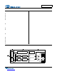
CS5345 TSTI NC NC NC SDOUT SCLK LRCK MCLK DGND VD OVFL INT 1.
CS5345 AIN1A AIN1B 11 12 Stereo Analog Input 1 (Input) - The full-scale level is specified in the ADC Analog Characteristics specification table. AGND 13 Analog Ground (Input) - Ground reference for the internal analog section. VA 14 Analog Power (Input) - Positive power for the internal analog section. AFILTA 15 Antialias Filter Connection (Output) - Antialias filter connection for the channel A ADC input.
CS5345 2. CHARACTERISTICS AND SPECIFICATIONS SPECIFIED OPERATING CONDITIONS AGND = DGND = 0 V; All voltages with respect to ground. Parameters DC Power Supplies: Symbol Min Nom Max Units VA VD VLS VLC TA 3.13 3.13 1.71 1.71 -10 5.0 3.3 3.3 3.3 - 5.25 (Note 1) 5.25 5.25 +70 V V V V C Analog Digital Logic - Serial Port Logic - Control Port Ambient Operating Temperature (Power Applied) Notes: 1. Maximum of VA+0.25 V or 5.25 V, whichever is less.
CS5345 ADC ANALOG CHARACTERISTICS Test conditions (unless otherwise specified): AGND = DGND = 0 V; VA = 3.13 V to 5.25 V; VD = 3.13 V to 5.25 V or VA + 0.25 V, whichever is less; VLS = VLC = 1.71 V to 5.25 V; TA = -10° to +70° C for Commercial; Input test signal: 1 kHz sine wave; measurement bandwidth is 10 Hz to 20 kHz; Fs = 48/96/192 kHz.; All connections as shown in Figure 7 on page 22. Line-Level Inputs Parameter Dynamic Performance for VA = 4.75 V to 5.
CS5345 DC Accuracy Gain Error Gain Drift - 100 10 - % ppm/°C 0.51*VA 6.12 0.57*VA 6.8 0.63*VA 7.48 Vpp k - 5 - % Line-Level Input Characteristics Full-scale Input Voltage Input Impedance Maximum Interchannel Input Impedance Mismatch (Note 4) Line-Level and Microphone-Level Inputs Commercial Grade Parameter Symbol Min Typ Max Unit - 0.1 - dB - 0.5 - 0.4 dB dB DC Accuracy Interchannel Gain Mismatch Programmable Gain Characteristics Gain Step Size Absolute Gain Step Error 4.
CS5345 ADC ANALOG CHARACTERISTICS (Continued) Microphone-Level Inputs Parameter Dynamic Performance for VA = 4.75 V to 5.25 V Symbol Min Typ Max Unit 77 74 83 80 - dB dB 65 62 71 68 - dB dB - -80 -60 -20 -74 - dB dB dB - -68 - dB 77 74 83 80 - dB dB 65 62 71 68 - dB dB - -80 -60 -20 -74 - dB dB dB - -68 80 - dB dB - 300 5 - % ppm/°C 0.013*VA - 0.017*VA 60 0.
CS5345 ADC DIGITAL FILTER CHARACTERISTICS Parameter (Notes 8, 10) Symbol Min Typ Max Unit 0 - 0.4896 Fs - - 0.035 dB 0.5688 - - Fs 70 - - dB - 12/Fs - s 0 - 0.4896 Fs - - 0.025 dB Single-Speed Mode Passband (-0.1 dB) Passband Ripple Stopband Stopband Attenuation Total Group Delay (Fs = Output Sample Rate) tgd Double-Speed Mode Passband (-0.1 dB) Passband Ripple Stopband Stopband Attenuation Total Group Delay (Fs = Output Sample Rate) tgd 0.
CS5345 PGAOUT ANALOG CHARACTERISTICS Test conditions (unless otherwise specified): AGND = DGND = 0 V; VA = 3.13 V to 5.25 V; VD = 3.13 V to 5.25 V or VA + 0.25 V, whichever is less; VLS = VLC = 1.71 V to 5.25 V; TA = -10° to +70° C; Input test signal: 1 kHz sine wave; Measurement bandwidth: 10 Hz to 20 kHz; Fs = 48/96/192 kHz; Synchronous mode; All connections as shown in Figure 7 on page 22. VA = 4.75 V to 5.
CS5345 PGAOUT ANALOG CHARACTERISTICS (Continued) VA = 3.13 V to 3.
CS5345 PGAOUT ANALOG CHARACTERISTICS (Continued) VA = 3.13 V to 5.25 V Parameter DC Accuracy with PGA Line Level Input Selected Symbol Interchannel Gain Mismatch Gain Error Gain Drift Min Typ Max Unit - 0.1 5 100 - dB % ppm/°C - 0.3 5 300 - dB % ppm/°C -0.1dB 100 - 180 - +0.
CS5345 DC ELECTRICAL CHARACTERISTICS AGND = DGND = 0 V, all voltages with respect to ground. MCLK=12.288 MHz; Fs=48 kHz; Master Mode. Parameter Symbol Min Typ Max Unit V V V V IA IA ID ID - 41 37 39 23 50 45 47 28 mA mA mA mA VA = 5 V VLS, VLC, VD=5 V IA ID - 0.50 0.54 - mA mA Power Consumption (Normal Operation) VA, VD, VLS, VLC = 5 V (Power-Down Mode) VA, VD, VLS, VLC = 3.3 V VA, VD, VLS, VLC = 5 V - - 400 198 4.2 485 241 - mW mW mW PSRR - 55 - dB VQ - 0.
CS5345 DIGITAL INTERFACE CHARACTERISTICS Test conditions (unless otherwise specified): AGND = DGND = 0 V; VLS = VLC = 1.71 V to 5.25 V. Parameters (Note 16) Symbol Min Typ Max Units VIH VIH VIH VIH VIL VIL VOH VOH VOL VOL Iin 0.8xVLS 0.8xVLC 0.7xVLS 0.7xVLC VLS-1.0 VLC-1.0 - - 0.2xVLS 0.2xVLC 0.4 0.4 ±10 1 V V V V V V V V V V A pF - - s High-Level Input Voltage VL = 1.71 V VL > 2.
CS5345 SWITCHING CHARACTERISTICS - SERIAL AUDIO PORT Logic ‘0’ = DGND = AGND = 0 V; Logic ‘1’ = VL, CL = 20 pF. (Note 18) Parameter Sample Rate Single-Speed Mode Double-Speed Mode Quad-Speed Mode Symbol Min Typ Max Unit Fs Fs Fs 4 50 100 - 50 100 200 kHz kHz kHz fmclk tclkhl 1.024 8 - 51.
CS5345 LRCK Output t slr SCLK Output t sdo SDOUT Figure 1. Master Mode Serial Audio Port Timing LRCK Input t slr t sclkh t sclkl SCLK Input t sdo t sclkw SDOUT Figure 2.
CS5345 Channel B - Right Channel A - Left LRCK SCLK SDATA MSB -1 -2 -3 -4 -5 +5 +4 +3 +2 +1 LSB MSB -1 -2 -3 -4 +5 +4 +3 +2 +1 LSB Figure 3. Format 0, Left-Justified up to 24-Bit Data Channel A - Left LRCK Channel B - Right SCLK SDATA MSB -1 -2 -3 -4 -5 +5 +4 +3 +2 +1 LSB MSB -1 -2 -3 -4 +5 +4 +3 +2 +1 LSB Figure 4.
CS5345 SWITCHING CHARACTERISTICS - CONTROL PORT - I²C FORMAT Inputs: Logic 0 = DGND = AGND = 0 V, Logic 1 = VLC, CL = 30 pF. Parameter Symbol Min Max Unit SCL Clock Frequency fscl - 100 kHz RESET Rising Edge to Start tirs 500 - ns Bus Free Time Between Transmissions tbuf 4.7 - µs Start Condition Hold Time (prior to first clock pulse) thdst 4.0 - µs Clock Low time tlow 4.7 - µs Clock High Time thigh 4.0 - µs tsust 4.
CS5345 SWITCHING CHARACTERISTICS - CONTROL PORT - SPI FORMAT Inputs: Logic 0 = DGND = AGND = 0 V, Logic 1 = VLC, CL = 30 pF. Parameter Symbol Min Max Units CCLK Clock Frequency fsck - 6.0 MHz RESET Rising Edge to CS Falling tsrs 500 - ns CS High Time Between Transmissions tcsh 1.
CS5345 3. TYPICAL CONNECTION DIAGRAM +3.3V to +5V 10 µF +3.3V to +5V 0.1 µF 0.1 µF VA VD 0.1 µF 10 µF VA 3.3 µF +1.8V to +5V 0.1 µF PGAOUTA VLS 3.
CS5345 4. APPLICATIONS 4.1 Recommended Power-Up Sequence 1. Hold RESET low until the power supply, MCLK, and LRCK are stable. In this state, the Control Port is reset to its default settings. 2. Bring RESET high. The device will remain in a low power state with the PDN bit set by default. The control port will be accessible. 3. The desired register settings can be loaded while the PDN bit remains set. 4. Clear the PDN bit to initiate the power-up sequence. 4.
CS5345 In both Master and Slave Modes, the external MCLK must be divided down based on the MCLK/LRCK ratio to achieve a post-divider MCLK/LRCK ratio of 256x for SSM, 128x for DSM, or 64x for QSM. Table 3 lists the appropriate dividers. MCLK/LRCK Ratio MCLK Dividers 64x - - ÷1 96x - - ÷1.5 128x - ÷1 ÷2 192x - ÷1.5 ÷3 256x ÷1 ÷2 ÷4 384x ÷1.5 ÷3 - 512x ÷2 ÷4 - 768x ÷3 - - 1024x ÷4 - - Mode SSM DSM QSM Table 3. MCLK Dividers 4.2.
CS5345 which could result in recording a DC level, possibly yielding clicks when switching between devices in a multichannel system. The high-pass filter continuously subtracts a measure of the DC offset from the output of the decimation filter. If the HPFFreeze bit (See “High-Pass Filter Freeze (Bit 1)” on page 33.) is set during normal operation, the current value of the DC offset for the each channel is frozen and this DC offset will continue to be subtracted from the conversion result.
CS5345 4.4 Analog Input Multiplexer, PGA, and Mic Gain The CS5345 contains a stereo 6-to-1 analog input multiplexer followed by a programmable gain amplifier (PGA). The input multiplexer can select one of six possible stereo analog input sources and route it to the PGA. Analog inputs 4A and 4B are able to insert a +32 dB gain stage before the input multiplexer, allowing them to be used for microphone-level signals without the need for any external gain.
CS5345 4.7 Control Port Description and Timing The control port is used to access the registers, allowing the CS5345 to be configured for the desired operational modes and formats. The operation of the control port may be completely asynchronous with respect to the audio sample rates. However, to avoid potential interference problems, the control port pins should remain static if no operation is required. The control port has two modes: SPI and I²C, with the CS5345 acting as a slave device.
CS5345 be connected through a resistor to VLC or DGND as desired. The state of the pins is sensed while the CS5345 is being reset. The signal timings for a read and write cycle are shown in Figure 11 and Figure 12. A Start condition is defined as a falling transition of SDA while the clock is high. A Stop condition is a rising transition while the clock is high. All other transitions of SDA occur while the clock is low.
CS5345 Receive byte, contents of selected register. Send acknowledge bit. Send stop condition. 4.8 Interrupts and Overflow The CS5345 has a comprehensive interrupt capability. The INT output pin is intended to drive the interrupt input pin on the host microcontroller. The INT pin may function as either an active high CMOS driver or an active low open-drain driver (see “Active High/Low (Bit 0)” on page 36).
CS5345 system logic supply (VLS or VLC) or may be powered from the analog supply (VA) via a resistor. In this case, no additional devices should be powered from VD. Power supply decoupling capacitors should be as near to the CS5345 as possible, with the low value ceramic capacitor being the nearest. All signals, especially clocks, should be kept away from the FILT+ and VQ pins in order to avoid unwanted coupling into the modulators. The FILT+ and VQ decoupling capacitors, particularly the 0.
CS5345 5. REGISTER QUICK REFERENCE This table shows the register names and their associated default values.
CS5345 6. REGISTER DESCRIPTION 6.1 Chip ID - Register 01h 7 PART3 6 PART2 5 PART1 4 PART0 3 REV3 2 REV2 1 REV1 0 REV0 Function: This register is Read-Only. Bits 7 through 4 are the part number ID, which is 1110b (0Eh), and the remaining bits (3 through 0) indicate the device revision as shown in Table 5 below. REV[2:0] Revision 001 A 010 B, C0 011 C1 Table 5. Device Revision 6.2 Power Control - Address 02h 7 Freeze 6.2.
CS5345 6.3 ADC Control - Address 04h 7 6 5 4 3 2 1 0 FM1 FM0 Reserved DIF Reserved Mute HPFFreeze M/S 6.3.1 Functional Mode (Bits 7:6) Function: Selects the required range of sample rates. FM1 FM0 0 0 Single-Speed Mode: 4 to 50 kHz sample rates Mode 0 1 Double-Speed Mode: 50 to 100 kHz sample rates 1 0 Quad-Speed Mode: 100 to 200 kHz sample rates 1 1 Reserved Table 7. Functional Mode Selection 6.3.
CS5345 6.4 MCLK Frequency - Address 05h 7 Reserved 6.4.1 6 MCLK Freq2 5 MCLK Freq1 4 MCLK Freq0 3 2 1 0 Reserved Reserved Reserved Reserved Master Clock Dividers (Bits 6:4) Function: Sets the frequency of the supplied MCLK signal. See Table 9 for the appropriate settings. MCLK Divider MCLK Freq2 MCLK Freq1 MCLK Freq0 ÷1 0 0 0 ÷ 1.5 0 0 1 ÷2 0 1 0 ÷3 0 1 1 ÷4 1 0 0 Reserved 1 0 1 Reserved 1 1 x Table 9. MCLK Frequency 6.
CS5345 6.7 Channel A PGA Control - Address 08h 7 Reserved 6.7.1 6 Reserved 5 Gain5 4 Gain4 3 Gain3 2 Gain2 1 Gain1 0 Gain0 Channel A PGA Gain (Bits 5:0) Function: Sets the gain or attenuation for the ADC input PGA stage. The gain may be adjusted from -12 dB to +12 dB in 0.5 dB steps. The gain bits are in two’s complement with the Gain0 bit set for a 0.5 dB step. Register settings outside of the ±12 dB range are reserved and must not be used. See Table 11 for example settings.
CS5345 PGASoft 0 0 1 1 PGAZeroCross 0 1 0 1 Mode Changes to affect immediately Zero Cross enabled Soft Ramp enabled Soft Ramp and Zero Cross enabled (default) Table 12. PGA Soft Cross or Zero Cross Mode Selection 6.8.2 Analog Input Selection (Bits 2:0) Function: These bits are used to select the input source for the PGA and ADC. Please see Table 13.
CS5345 6.10.1 Clock Error (Bit 3) Function: Indicates the occurrence of a clock error condition. 6.10.2 Overflow (Bit 1) Function: Indicates the occurrence of an ADC overflow condition. 6.10.3 Underflow (Bit 0) Function: Indicates the occurrence of an ADC underflow condition. 6.
CS5345 7. PARAMETER DEFINITIONS Dynamic Range The ratio of the rms value of the signal to the rms sum of all other spectral components over the specified bandwidth. Dynamic Range is a signal-to-noise ratio measurement over the specified bandwidth made with a -60 dBFS signal. 60 dB is added to resulting measurement to refer the measurement to full scale. This technique ensures that the distortion components are below the noise level and do not affect the measurement.
CS5345 0 -10 -20 -30 -40 -50 -60 -70 -80 -90 -100 -110 -120 -130 -140 Amplitude (dB) Amplitude (dB) 8. FILTER PLOTS 0.0 0.1 0.2 0.3 0.4 0.5 0.6 0.7 0.8 0.9 1.0 0 -10 -20 -30 -40 -50 -60 -70 -80 -90 -100 -110 -120 -130 -140 0.40 0.42 0.44 Frequency (norm alized to Fs) 0 0.10 -1 0.08 -2 0.06 -3 -4 -5 -6 -7 0.58 0.60 0.00 -0.02 -0.04 -0.06 -0.08 -0.10 0.46 0.47 0.48 0.49 0.5 0.51 0.52 0.53 0.54 0 0.55 Figure 15. Single-Speed Transition Band (Detail) 0.2 0.3 0.4 0.5 0.
0 0.10 -1 0.08 -2 0.06 Amplitude (dB) Amplitude (dB) CS5345 -3 -4 -5 -6 -7 0.04 0.02 0.00 -0.02 -0.04 -8 -0.06 -9 -0.08 -10 0.46 0.47 0.48 0.49 0.50 0.51 -0.10 0.00 0.05 0.52 Frequency (norm alized to Fs) 0 -10 -20 -30 -40 -50 -60 -70 -80 -90 -100 -110 -120 -130 -140 0.1 0.2 0.3 0.4 0.5 0.6 0.7 0.8 0.15 0.20 0.25 0.30 0.35 0.40 0.45 0.50 Figure 20. Double-Speed Passband Ripple Amplitude (dB) Amplitude (dB) Figure 19. Double-Speed Transition Band (Detail) 0.0 0.
CS5345 9. PACKAGE DIMENSIONS 48L LQFP PACKAGE DRAWING E E1 D D1 1 e B A A1 L DIM A A1 B D D1 E E1 e* L MIN --0.002 0.007 0.343 0.272 0.343 0.272 0.016 0.018 0.000° * Nominal pin pitch is 0.50 mm INCHES NOM MAX MIN 0.055 0.063 --0.004 0.006 0.05 0.009 0.011 0.17 0.354 0.366 8.70 0.28 0.280 6.90 0.354 0.366 8.70 0.28 0.280 6.90 0.020 0.024 0.40 0.24 0.030 0.45 4° 7.000° 0.00° *Controlling dimension is mm. MILLIMETERS NOM MAX 1.40 1.60 0.10 0.15 0.22 0.27 9.0 BSC 9.30 7.0 BSC 7.10 9.0 BSC 9.30 7.
CS5345 11.ORDERING INFORMATION Product CS5345 CDB5345 Description 24-bit, 192 kHz Stereo Audio ADC Package Pb-Free 48-LQFP CS5345 Evaluation Board Grade Temp Range Yes Commercial -10° to +70° C No - - Container Order # Tray CS5345-CQZ Tape & Reel CS5345-CQZR - CDB5345 12.REVISION HISTORY Release F1 F2 F3 F4 Changes – Removed the MAP auto-increment functional description from the Control Port Description and Timing section beginning on page 27.