
User Manual


DS687F4 7
CS5343/4
Draft
2/1/11
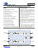
DIGITAL FILTER CHARACTERISTICS
Notes:
6. Response shown is for Fs equal to 48 kHz. Filter characteristics scale with Fs.
DC ELECTRICAL CHARACTERISTICS
GND = 0 V, all voltages with respect to 0 V. MCLK=12.288 MHz; Master Mode.
Notes:
7. Device enters power-down mode when MCLK is held static.
8. Valid with the recommended capacitor values on FILT+ and VQ as shown in the Typical Connection
Diagram.
Parameter Symbol Min Typ Max Unit
All Speed Modes
Passband (-0.1 dB) 0 - 0.489 Fs
Passband Ripple -0.031 - 0.031 dB
Stopband 0.560 - - Fs
Stopband Attenuation 60 - - dB
Total Group Delay (Fs = Output Sample Rate) t
gd
-12/Fs- s
High-Pass Filter Characteristics
Frequency Response -3.0 dB
-0.13 dB (Note 6)
-1
20
-
-
Hz
Hz
Phase Deviation @ 20 Hz (Note 6) -10-Deg
Passband Ripple - - 0 dB
Parameter Symbol
VA = 3.3 V VA = 5.0 V
Min Typ Max Min Typ Max Unit
Power Supply Current (Normal Operation) I
A
- 11 15 - 12 17 mA
Power Supply Current (Power-Down Mode) (Note 7) I
A
-10--40 - uA
Power Consumption (Normal Operation)
(Power-Down Mode) (Note 7)
-
-
-
-
36
<1
50
-
-
-
60
<1
85
-
mW
mW
Parameter Symbol Min Typ Max Unit
Power Supply Rejection Ratio (1 kHz) (Note 8)
PSRR - 65 - dB
V
Q
Nominal Voltage
Output Impedance
-
-
0.44xVA
25
-
-
V
k
Filt+ Nominal Voltage
Output Impedance
Maximum allowable DC current source/sink
-
-
-
VA
220
2.5
-
-
-
V
k
uA