
User Manual

DS138F6 13
CS5330A/31A
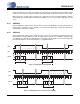
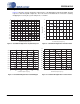
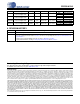
3.1.11 Digital Filter
Figures 5 through 8 show the attenuation characteristics of the digital filter included in the ADC. The filter
response scales linearly with sample rate. The x-axis has been normalized to Fs and can be scaled by
multiplying the x-axis by the system sample rate, i.e. 48 kHz.
0
-10
-20
-30
-40
-50
-60
-70
-80
-90
-100
-110
-120
0.0 0.1 0.2 0.3 0.4 0.5 0.6 0.7 0.8 0.9 1.0
Normalized Input Frequency
2
0
-2
-4
-6
-8
-10
.46 .47 .48 .49 .50 .51 .52 .53
.5
4
Magnitude (dB)
Normalized Input Frequency
Figure 5. CS5330A/31A Digital Filter Stopband Rejection Figure 6. CS5330A/31A Digital Filter Transition Band
0.05
0.04
0.03
0.02
0.01
0.00
-0.01
-0.02
-0.03
-0.04
-0.05
0 0.1 0.2 0.3 0.4 0.5
Normalized Input Frequency
0.0
-10.0
-20.0
-30.0
-40.0
-50.0
-60.0
-70.0
-80.0
-90.0
-
100.0
0.40 0.45 0.50 0.60 0.65 0.7
0
Normalized Input Frequency
Figure 7. CS5330A/31A Digital Filter Passband Ripple Figure 8. CS5330A/31A Digital Filter Transition Band