
User guide


4-10 Copyright 2013 Cirrus Logic, Inc. DS810UM6
Digital Audio Output Port Description
CS4953x4/CS4970x4 System Designer’s Guide
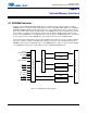
To summarize the XMTA/XMITB S/PDIF output pins can be configured as:
•I
2
S output - Default
• S/PDIF Transmitter - Sent configuration from Table 4-10
• DSP Bypass - Send configuration from Table 4-11
The DSP Bypass configuration is typically used to route a S/PDIF stream from input to the output for
recording applications or as a PCM bypass for dual-zone applications. A soft reset is required when
switching between any of the above modes.
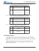
Table 4-9. S/PDIF Transmitter Pins
Pin Name Pin Description
LQFP-144
Pin #
LQFP-128
Pin #
Pin Type
XMTA_IN
S/PDIF Input for XMTA mux The
XMTA_IN S/PDIF inputs is muxed with
XMTA to allow switching the S/PDIF
output between the internal and
external sources
2 - Input
XMTB_IN
S/PDIF Input for XMTB mux The
XMTB_IN S/PDIF inputs is muxed with
XMTB to allow switching the S/PDIF
output between the internal and
external sources
92 - Input
DAO1_DATA3/XMTA S/PDIF Audio Output A 15 47 Output
DAO2_DATA3/XMTB S/PDIF Audio Output B 5 35 Output
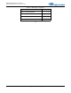
Table 4-10. S/PDIF Transmitter Configuration
Description Hex Message
Enable S/PDIF on Output A on DAO1_DATA3/
XMTA (MCLK=256 Fs)
0x8100002e
0x00005080
Enable S/PDIF on Output A on DAO1_DATA3/
XMTA (MCLK=512 Fs)
0x8100002e
0x00005080
0x8180003C
0xFFFFFF8F
0x8140003C
0x00000010
Enable S/PDIF on Output A on DAO1_DATA3/
XMTA (MCLK=1024 Fs)
0x8100002e
0x00005080
0x8180003C
0xFFFFFF8F
0x8140003C
0x00000030
Enable S/PDIF on Output B on DAO2_DATA3/
XMTB (MCLK=256 Fs)
0x8100002f
0x00005080
Enable S/PDIF on Output B on DAO2_DATA3/
XMTB (MCLK=512 Fs)
0x8100002f
0x00005080
0x8180003C
0xFFFFFF8F
0x8140003C
0x00000010
Enable S/PDIF on Output B on DAO2_DATA3/
XMTB (MCLK=1024 Fs)
0x8100002f
0x00005080
0x8180003C
0xFFFFFF8F
0x8140003C
0x00000030