
User guide


3-4 Copyright 2013 Cirrus Logic, Inc. DS810UM6
DAI Hardware Configuration
CS4953x4/CS4970x4 System Designer’s Guide
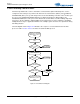
the right subframe is presented when DAIn_LRCLK is low. The left-justified format can also be
programmed for data to be valid on the falling edge of DAIn_SCLK.
Figure 3-2. Left-justified Format (Rising Edge Valid SCLK)
3.3 DAI Hardware Configuration
DAI hardware configuration must be done at design time using DSP Composer. See Chapter 8, "DSP
Condenser".for more details.
3.3.1 DAI Hardware Naming Convention
The naming convention of the input hardware configuration is as follows:
INPUT A B C D
Where A, B, C, and D are the parameters used to fully define the input port. The parameters are defined
as follows:
• A - Data Format
• B - SCLK Polarity
• C - LRCLK Polarity.
• D - DAI Mode
Table 3-3, Table 3-4, Table 3-5, and Table 3-6 show the different values for each parameter as well as the
hex message that needs to be sent to configure the port. When creating the hardware configuration
message, only one hex message should be sent per parameter.
DAIn_LRCLK
DAIn_SCLK
Left Channel
Right Channel
DAIn_DATA
+3 +2 +1 LSB+5 +4
MSB
-1
-2 -3 -4 -5
+3 +2 +1+5 +4
-1 -2 -3 -4
LSB
MSB