
User guide


I2C Port
CS4953x4/CS4970x4 System Designer’s Guide
DS810UM6 Copyright 2013 Cirrus Logic, Inc 2-14
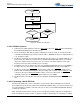
Figure 2-13. Stop Condition with ACK and NACK
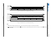
If a Slave can’t receive or transmit another complete byte of data until it has performed some other
function, for example servicing an internal interrupt, it can hold the SCP1_CLK line low to force the Master
into a wait state. Data transfer then continues when the Slave is ready for another byte of data and
releases SCP1_CLK.
2.5.3 I
2
C Messaging
Messaging to the CS4953x4/CS4970x4 using the I
2
C bus requires usage of all the information provided in
the above I
2
C Section 2.5.1 “I
2
C System Bus Description” on page 10 and Section 2.5.2 “I
2
C Bus
Dynamics” on page 11. Every I
2
C transaction to the CS4953x4/CS4970x4 involves 4-byte words used for
control and application image download. A detailed description of the serial SPI communication mode is
provided in this section. This includes:
• A flow diagram and description for a serial I
2
C write
• A flow diagram and description for a serial I
2
C read
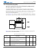
2.5.3.1 SCP1_BSY Behavior
The SCP1_BSY signal is not part of the I
2
C protocol, but it is provided so that the Slave can signal to the
Master that it cannot receive any more data. A falling edge of the SCP1_BSY
signal indicates the Master
must halt transmission. Once the SCP1_BSY
signal goes high, the suspended transaction may continue.
It is important for the host to obey the SCP1_BSY
pin status for proper communication with the DSP.
Stop
SCP1_CLK
SCP1_SDA
Data Byte
ACK
M
S MWrite
Read
S
M M
Stop
SCP1_CLK
SCP1_SDA
Data Byte
NACK
M
S M
Write
Read
S
M M
M = Master Drives SDA
S = Slave Drives SDA