
User guide


DS810UM6 Copyright 2013 Cirrus Logic, Inc 2-8
SPI Port
CS4953x4/CS4970x4 System Designer’s Guide
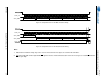
Figure 2-5. Sample Waveform for SPI Write Functional Timing
Figure 2-6. Sample Waveform for SPI Read Functional Timing
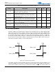
Note:
1. IRQ remains low until the rising edge of the clock for the last bit of the last byte to be read from the SPI Slave.
2. After going high, IRQ remains high until the CS
signal is raised to end the SPI transaction. If there are more bytes to read, IRQ will fall after
CS
has gone high.
SCP1_CLK
SCP1_MOSI
Data Byte 3 (MSB)7-bit Address
R
/W
Data Byte 2 Data Byte 1 Data Byte 0 (LSB)
SCP1_CS
SCP1_CLK
SCP1_MOSI
Data Byte 3 (MSB)
7-bit Address
R
/W
Data Byte 2 Data Byte 1 Data Byte 0 (LSB)
SCP1_CS
SCP1_MISO
SCP1_IRQ