
User guide


Overview
CS4953x4/CS4970x4 System Designer’s Guide
DS810UM6 Copyright 2013 Cirrus Logic, Inc 1-1
Chapter 1
Operational Modes
1.1 Overview
The CS4953x4/CS4970x4 DSP has several operational modes that can be used to conform to many
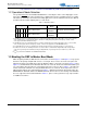
system configurations. The DSP is configured to Master Boot as shown in Figure 1-1 in order to simplify
connectivity and to reduce the complexity of the microcontroller code used in the system.
Figure 1-1. Operation Mode Block Diagram
The DSP is configured to boot from external serial SPI Flash when reset is released. Once the DSP is
booted, it turns into an intelligent Slave device. The DSP will swap out decoders from external SPI Flash
when stream changes without the necessity of interacting with the host. The DSP will change any mid- or
post-processing module with a single command from the host. The DSP takes on most of the control
functionality from the microcontroller. This significantly reduces the microcontroller development effort
thereby reducing time to market of the end product.
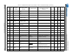
1.1.1 Supported Serial Flash Devices
Cirrus logic recommends SPI serial flash devices with a minimum storage capacity of 8 Mbits. The Cirrus
recommended flash devices are:
• SST25VF080B (tested) - See the data sheet for this device at:
http://www.microchip.com/wwwproducts/Devices.aspx?dDocName=en549423
• EN25P32 (tested) - See the data sheet for this device at:
http://www.eonssi.com/upfile/p2008929182330.pdf
• M25P80 (tested) - See the data sheet for this device at:
http://www.icbase.com/pdf/STM/STM30070501.pdf
• SST25LFxxx
• AT45DB041D - See the data sheet for this device at:
CS4953x4/CS4970x4
(Master at Boot,
Intelligent Slave after
Boot)
Ext. Serial Flash
SCP2
System Host
Controller
(Master after
Boot)
SCP1
Control Bus
(SPI or 1
2
C)
(SPI)