
User Manual

CS4953xx Data Sheet
32-bit Audio Decoder DSP Family
DS705F2 12
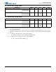
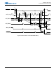
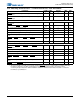
5.7 Switching Characteristics—RESET
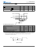
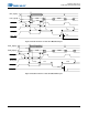
Figure 1. RESET Timing
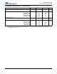
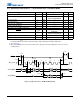
5.8 Switching Characteristics — XTI
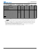
Figure 2. XTI Timing
Parameter Symbol Min Max Unit
RESET minimum pulse width low
T
rstl
1—μs
All bidirectional pins high-Z after RESET low
T
rst2z
/m 100 ns
Configuration pins setup before RESET high
T
rstsu
50 — ns
Configuration pins hold after RESET high
T
rsthld
20 — ns
Parameter Symbol Min Max Unit
External Crystal operating frequency
1
1. Part characterized with the following crystal frequency values: 12.288 and 24.576
F
xtal
12.288 24.576 MHz
XTI period
T
clki
41 81.4 ns
XTI high time
T
clkih
16.4 /m ns
XTI low time
T
clkil
16.4 — ns
External Crystal Load Capacitance (parallel resonant)
2
2. C
L
refers to the total load capacitance as specified by the crystal manufacturer. Crystals which require a C
L
outside
this range should be avoided. The crystal oscillator circuit design should follow the crystal manufacturer’s
recommendation for load capacitor selection.
C
L
10 18 pF
External Crystal Equivalent Series Resistance
ESR — 50 Ω
RESET#
T
rst2z
T
rstl
T
rstsu
T
rsthld
HS[3:0]
All Bidirectional
Pins
t
clkih
t
clkil
T
clki
XTI