
User Manual

CS4953xx Data Sheet
32-bit Audio Decoder DSP Family
DS705F2 11
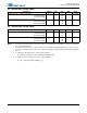
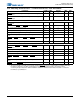
5.5 Thermal Data (144-pin LQFP)
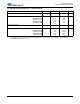
5.6 Thermal Data (128-pin LQFP)
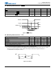
Notes: 1. Two-layer board is specified as a 76 mm X 114 mm, 1.6 mm thick FR-4 material with 1-oz copper covering 20 %
of the top & bottom layers.
2. Four-layer board is specified as a 76 mm X 114 mm, 1.6 mm thick FR-4 material with 1-ounce copper covering
20 % of the top & bottom layers and 0.5-ounce copper covering 90 % of the internal power plane and ground plane
layers.
3. To calculate the die temperature for a given power dissipation
Τ
j
= Ambient Temperature + [ (Power Dissipation in Watts) * θ
ja
]
4. To calculate the case temperature for a given power dissipation
Τ
c
= Τ
j
- [ (Power Dissipation in Watts) * ψ
jt
]
Parameter Symbol Min Typ Max Unit
Thermal Resistance (Junction to Ambient)
Two-layer Board
1
Four-layer Board
2
θ
ja
—
—
48
40
—
—
°C / Watt
Thermal Resistance (Junction to Top of Package)
Two-layer Board
1
Four-layer Board
2
ψ
jt
—
—
.39
.33
—
—
°C / Watt
Parameter Symbol Min Typ Max Unit
Thermal Resistance (Junction to Ambient)
Two-layer Board
1
Four-layer Board
2
θ
ja
—
—
53
44
—
—
°C / Watt
Thermal Resistance (Junction to Top of Package)
Two-layer Board
1
Four-layer Board
2
ψ
jt
—
—
.45
.39
—
—
°C / Watt