
Manual


7-5 Copyright 2010 Cirrus Logic, Inc. DS732UM10
Digital Audio Output Port Description
CS4953xx Hardware User’s Manual
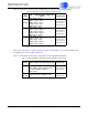
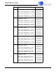
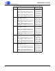
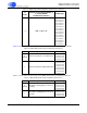
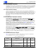
Table 7-2 shows values and messages for DAO output clock mode configuration parameters.
Please refer to the Table 7-3, Table 7-4, Table 7-5, Table 7-6, and Table 7-7 for a visual example of the
clocking directions for the settings in Table 7-2.
Table 7-3 shows values and messages for the data format configuration parameters.
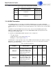
Table 7-2. Output Clock Mode Configuration (Parameter A)
A
Value
DAO 1 & 2 Modes (MCLK, LRCLK and
SCLK)
a
a. A0 always goes with parameter B0. B0 is located in Table
7-3..
Hex Message
0
(default)
DAO_MCLK - Slave
DAO1_LRCLK - Slave
DAO1_SCLK - Slave
DAO2_LRCLK - Slave
DAO2_SCLK - Slave
0x8140002C
0x00002000
0x8100002D
0x00002000
1
DAO_MCLK - Slave
DAO1_LRCLK - Master
DAO1_SCLK - Master
DAO2_LRCLK - Master
DAO2_SCLK - Master
0x8180002C
0xFFFFDFFF
0x8180002D
0xFFFFDFFF
2
DAO_MCLK - Slave
DAO1_LRCLK - Slave
DAO1_SCLK - Slave
DAO2_LRCLK - Master
DAO2_SCLK - Master
0x8140002C
0x00002000
0x8180002D
0xFFFFDFFF
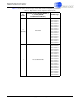
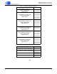
Table 7-3. DAO1 & DAO2 Clocking Relationship Configuration (Parameter B)
B
Value
DAO1 & DAO2 Clocking Relationship Hex Message
0
DAO2 dependent on DAO1 clocks
Note:: DA02_LRCLK & DA02_SCLK
are driven by DA01_LRCLK &
DA01_SCLK
0x8140002B
0x00002000
1
(default)
DAO2 independent of DAO1 clocks
0x8180002B
0xFFFFDFFF