
Manual

6-1 Copyright 2010 Cirrus Logic, Inc. DS732UM10
Description of Digital Audio Input Port when Configured for DSD Input
CS4953xx Hardware User’s Manual
Chapter 6
Direct Stream Data (DSD) Input Interface
CS4953xx is capable of accepting Direct Stream Data (DSD) audio data directly. DSD data differs from
PCM in that audio is provided as a contiguous stream of 1’s and 0’s on a single line. There is no framing
clock (LRCLK), and there is only one channel per line. The CS4953xx supports internal conversion of
DSD data to PCM which can then be processed by the DSP.
6.1 Description of Digital Audio Input Port when Configured for
DSD Input
The CS4953xx DSD port is designed to accept DSD audio data from up to 6 pins simultaneously (6
channels total)
DSD features include:
• Six DSD Input Pins
• One Shared DSD_CLK for All Data Pins
• Supports 44.1 kHz (1 Fs), 88.2 kHz (2 Fs), and 176.4 kHz (4 Fs) Sample Rates
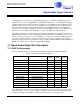
6.1.1 DSD Pin Description
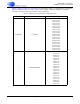
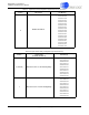
Table 6-1 shows the mnemonic and pin description of the pins associated with the DSD port on
CS4953xx.
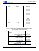
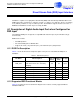
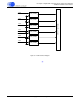
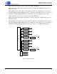
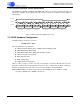
6.1.2 Supported DSD Functional Blocks
Figure 6-1 below shows the functional block diagram of the features currently supported with the
CS4953xx DSD Port.
Table 6-1. DSDl Audio Input Port
Pin Name Pin Description
LQFP-144
Pin #
LQFP-128
Pin #
Pin Type
DSD_CLK
Bit clock used for latching the DSD
audio data. This clock is shared by
DSD[5:0].
137 29 Input
DSD0 DSD Audio Input 0 135 27 Input
DSD1 DSD Audio Input 1 134 26 Input
DSD2 DSD Audio Input 2 132 24 Input
DSD3 DSD Audio Input 3 131 23 Input
DSD4 DSD Audio Input 4 142 34 Input
DSD5 DSD Audio Input 5 138 30 Input