
Manual


Digital Audio Input Port Description
CS4953xx Hardware User’s Manual
DS732UM10 Copyright 2010 Cirrus Logic, Inc 5-4
5.1.4 Digital Audio Formats
The DAI has 5 stereo data input pins that are fully configurable including support for I
2
S, and left-justified
formats. DAI ports are programmed for slave operation, where DAIn_LRCLK and DAIn_SCLK are inputs
only. This subsection describes some common audio formats that CS4953xx supports. It should be noted
that the input ports use up to 32-bit PCM resolution and 16-bit compressed data word lengths.
5.1.4.1 I
2
S Format
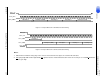
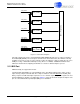
Figure 5-2 illustrates the I
2
S format. For I
2
S, data is presented most-significant bit (MSB) first, one SCLK
delay after the transition of DAIn_LRCLK, and is valid on the rising edge of DAIn_SCLK. For the I
2
S
format, the left subframe is presented when DAIn_LRCLK is low, and the right subframe is presented
when DAIn_LRCLK is high.
Figure 5-2. I
2
S format (Rising Edge Valid SCLK)
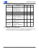
Table 5-2. Bursty Data Input (BDI) Pins
Pin Name Pin Description
LQFP-144
Pin #
LQFP-128
Pin #
Pin Type
BDI_REQ
Data Request, Active Low
BDI_REQ is the bursty delivery
flow control output for bursty
audio data. It indicates whether
the DSP can accept more data.
140 32 Output
BDI_CLK
Bit Clock 2 Bursty Audio Input
Bit Clock
BDI_CLK is the bit clock input
for the bursty serial audio data
on BDI_DATA.
141 33 Input
BDI_DATA
Compressed Audio Bursty
Input Data
BDI_DATA is the serial bursty
audio data input that
corresponds to the BDI_CLK
serial bit clock..
142 34 Input
DAO_LRCLK
DAO_SCLK
Left Channel
Right Channel
DAO_DATA
+3 +2 +1 LSB+5 +4
MSB-1-2-3-4-5
+3 +2 +1
LSB
+5 +4
MSB-1-2-3-4