
Manual

Digital Audio Input Port Description
CS4953xx Hardware User’s Manual
DS732UM10 Copyright 2010 Cirrus Logic, Inc 5-2
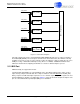
5.1.2 Supported DAI Functional Blocks
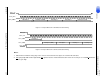
The CS4953xx DAI has many functional blocks for realizing various audio system configurations. The use
of these functions is dependent on the firmware currently available on the CS4953xx. Figure 5-1 shows
the functional block diagram of the features currently supported with the CS4953xx DAI.
DAI1_DATA0
PCM or Compressed Audio Input Data
0 PCM Audio Input Data 0
Serial data input that can accept PCM
audio data that is synchronous to
DAI_SCLK1/DAI_LRCLK1 or
DAO1_SCLK/DAO1_LRCLK..
135 27 Input
DAI1_DATA1 PCM Audio Input Data 1 134 26 Input
DAI1_DATA2 PCM Audio Input Data 2 132 24 Input
DAI1_DATA3 PCM Audio Input Data 3 131 23 Input
DAI2_LRCLK
Sample Rate Clock 2 PCM Audio Input
Sample Rate (LeftRight) Clock
DAI2_LRCLK is the sample rate input
clock for the serial PCM audio data on
DAI2_DATA.
140 32 Input
DAI2_SCLK
Bit Clock 2 PCM Audio Input Bit Clock
DAI2_SCLK is the bit clock input for
the serial PCM audio data on
DAI2_DATA.
141 33 Input
DAI2_DATA or
DAI1_DATA4
PCM or Compressed Audio Input Data
PCM Audio Input Data
DAI2_DATA is the PCM audio data
input synchronous to DAI2_SCLK/
DAI2_LRCLK
142 34 Input
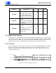
Table 5-1. Digital Audio Input Port (Continued)
Pin Name Pin Description
LQFP-144
Pin #
LQFP-128
Pin #
Pin Type