
Manual

DS732UM10 Copyright 2010 Cirrus Logic, Inc. v
Figures
CS4953xx Hardware User’s Manual
Chapter 8. External Memory Interfaces...............................................................8-1
8.1 SDRAM Controller . . . . . . . . . . . . . . . . . . . . . . . . . . . . . . . . . . . . . . . . . . . . . . . . . . . . . . . . . . .8-1
8.2 Flash Memory Controller. . . . . . . . . . . . . . . . . . . . . . . . . . . . . . . . . . . . . . . . . . . . . . . . . . . . . .8-2
8.2.1 Flash Controller Interface ...............................................................................................8-2
8.3 SDRAM/Flash Controller Interface . . . . . . . . . . . . . . . . . . . . . . . . . . . . . . . . . . . . . . . . . . . . . .8-2
8.3.1 SDRAM/Flash Interface Signals.....................................................................................8-2
8.3.2 Configuring SDRAM/Flash Parameters..........................................................................8-4
Chapter 9. System Integration..............................................................................9-1
9.1 Typical Connection Diagrams. . . . . . . . . . . . . . . . . . . . . . . . . . . . . . . . . . . . . . . . . . . . . . . . . .9-1
9.2 Pin Description. . . . . . . . . . . . . . . . . . . . . . . . . . . . . . . . . . . . . . . . . . . . . . . . . . . . . . . . . . . . .9-10
9.2.1 Power and Ground .......................................................................................................9-10
9.2.1.1 Power...........................................................................................................9-10
9.2.1.2 Ground.........................................................................................................9-10
9.2.1.3 Decoupling...................................................................................................9-11
9.2.2 PLL Filter ......................................................................................................................9-11
9.2.2.1 Analog Power Conditioning .........................................................................9-11
9.2.3 PLL ...............................................................................................................................9-12
9.3 Clocking . . . . . . . . . . . . . . . . . . . . . . . . . . . . . . . . . . . . . . . . . . . . . . . . . . . . . . . . . . . . . . . . . .9-12
9.4 Control . . . . . . . . . . . . . . . . . . . . . . . . . . . . . . . . . . . . . . . . . . . . . . . . . . . . . . . . . . . . . . . . . . .9-13
9.4.1 Operational Mode.........................................................................................................9-13
9.5 144-Pin LQFP Pin Assigments . . . . . . . . . . . . . . . . . . . . . . . . . . . . . . . . . . . . . . . . . . . . . . . .9-15
9.6 128-Pin LQFP Pin Assigments . . . . . . . . . . . . . . . . . . . . . . . . . . . . . . . . . . . . . . . . . . . . . . . .9-16
9.7 Pin Assignments . . . . . . . . . . . . . . . . . . . . . . . . . . . . . . . . . . . . . . . . . . . . . . . . . . . . . . . . . . .9-17
Revision History . . . . . . . . . . . . . . . . . . . . . . . . . . . . . . . . . . . . . . . . . . . . . . . . . . . . . . . . . . . . . . .9-29
Figures
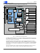
Figure 1-1. CS4953xx Chip Functional Block Diagram .................................................................................1-2
Figure 2-1. Operation Mode Block Diagrams ................................................................................................2-2
Figure 2-2. Host Controlled Master Boot.......................................................................................................2-5
Figure 2-3. Slave Boot Sequence .................................................................................................................2-8
Figure 2-4. Master Boot Sequence Flowchart.............................................................................................2-13
Figure 2-5. Soft Boot Sequence Flowchart .................................................................................................2-15
Figure 2-6. Soft Boot Example Flowchart....................................................................................................2-16
Figure 3-1. Serial Control Port Internal Block Diagram .................................................................................3-2
Figure 3-2. Block Diagram of I
2
C System Bus ..............................................................................................3-3
Figure 3-3. I
2
C Start and Stop Conditions.....................................................................................................3-4
Figure 3-4. I
2
C Address with ACK and NACK...............................................................................................3-5
Figure 3-5. Data Byte with ACK and NACK ..................................................................................................3-6
Figure 3-6. Repeated Start Condition with ACK and NACK..........................................................................3-6
Figure 3-7. Stop Condition with ACK and NACK...........................................................................................3-7