
Manual


I2C Port
CS4953xx Hardware User’s Manual
DS732UM10 Copyright 2010 Cirrus Logic, Inc 3-8
3.3.3.2 Performing a Serial I
2
C Write
Information provided in this section is intended as a functional description indicating how to use the
configured serial control port to perform a I
2
C write from an external device (master) to the CS4953xx
DSP (slave). The system designer must ensure that all timing constraints of the I
2
C write cycle are met
(see the CS4953xx datasheet for timing specifications). When writing to the CS4953xx, the same protocol
described in this section will be used when writing single-word messages to the boot firmware, writing
multiple-word overlay images to the boot firmware, and writing multiple-word messages to application
firmware. The examples given can therefor be expanded to fit any I
2
C writing situation.
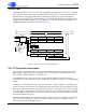
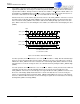
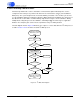
The flow diagram shown in Figure 3-8 illustrates the sequence of events that define the I
2
C write protocol
for SCP1. Section 3.4.3.2..describes the Serial I
2
C Write protocol.
Figure 3-8. I
2
C Write Flow Diagram
MORE DATA?
SEND I2C START:
DRIVE SCP1_SDA LOW
WHILE SCP1_CLK IS
HIGH
WRITE ADDRESS BYTE
0x80
N
SEND DATABYTE
I2C STOP:
DRIVE SCP1_SDA HIGH
WHILE SCP1_CLK IS
HIGH
Y
SCP1_BSY
(LOW)?
N
Y
Y
N
4 BYTES SENT?
SCP1_SDA ==
ACK?
Y
N
EXIT (ERROR)
SCP1_SDA ==
ACK?
Y
N
EXIT (ERROR)