
Manual

2-13 Copyright 2010 Cirrus Logic, Inc. DS732UM10
Master Boot Procedure
CS4953xx Hardware User’s Manual
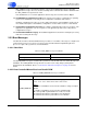
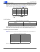
Table 2-9 is a quick reference showing the different boot commands understood by the CS4953xx, in
mnemonic and actual hex value, used in CS4953xx boot sequences.
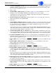
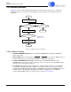
2.4 Master Boot Procedure
Note: Master Boot is currently not supported in the O/S
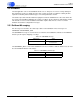
A master boot sequence is initiated immediately after the rising edge of RESET
. The location of the
overlay to boot is outlined in Table 2-1. Once the rising edge of RESET
has occurred, the CS4953xx will
load a single overlay from address 0x0. It should be noted that the loaded overlay must reconfigure one of
the control ports to be slave to the bus for a system host controller to configure the part. Thus, this type of
boot process will be useful in systems without a system host controller or with a simple controller that only
performs a monitoring task. Currently this mode is not used for any applications.
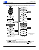
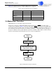
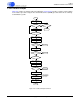
Figure 2-4. Master Boot Sequence Flowchart
Table 2-9. Boot Command Messages for CS4953xx
MNEMONIC VALUE DETAILED TABLE
SLAVE_BOOT 0x8000 0000 Table 2-2
HCMB_PARALLEL 0xE0== ==== Table 2-3
HCMB_I
2
C
0xC0== ==== Table 2-4
HCMB_SPI 0xD=== ==== Table 2-5
SOFT_RESET 0x40 00 00 00 Table 2-7
Start
RESET (Low)
RESET (High)
Done
Set HS[4:0] Pins For
Operational Mode