
User guide

25 DS1057F1
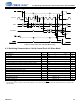
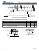
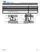
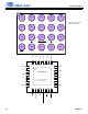
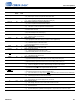
6 Package Dimensions
7. Controlling dimensions are in millimeters.
8. Dimensioning and tolerancing per ASME Y 14.5M.
9. Dimension “b” applies to the solder sphere diameter and is measured at the midpoint between the package body
and the seating plane.
10.Recommended reflow profile is per JEDEC/IPC J-STD-020
.
aaa Package edge tolerance 0.05
bbb Wafer flatness 0.1
ccc Coplanarity 0.03
ddd Ball/bump offset (package) 0.15
eee Ball/bump offset (ball) 0.05
1.Basic spacing between centers.
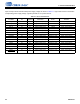
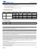
Table 6-2. QFN Package Dimension
MILLIMETERS INCHES
DIM MIN NOM MAX MIN NOM MAX
A 0.80 0.90 1.00 0.031 0.035 0.039
A1 0.00 0.02 0.05 0.000 0.001 0.002
A3 0.20 REF 0.008 REF
b 0.20 0.25 0.30 0.008 0.010 0.012
D 4.00 BSC 0.157 BSC
D2 2.60 2.70 2.80 0.102 0.106 0.110
e 0.50 BSC 0.020 BSC
E 4.00 BSC 0.157 BSC
E2 2.60 2.70 2.80 0.102 0.106 0.110
L 0.30 0.40 0.50 0.012 0.016 0.020
aaa 0.15 0.006
bbb 0.10 0.004
ddd 0.05 0.002
eee 0.08 0.003
Table 6-1. WLCSP Package Dimension (Cont.)
Symbol Description Dimensions
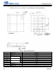
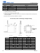
24-PIN QFN (4 mm x 4 mm Body) Package Drawing