
User guide

DS1057F1 18
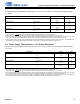
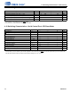
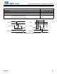
4.11 Switching Characteristics—Serial Control Port—I2C Slave Mode
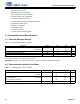
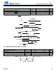
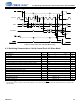
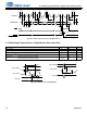
Figure 4-5. Serial Control Port—SPI Slave Mode Timing
4.11 Switching Characteristics—Serial Control Port—I
2
C Slave Mode
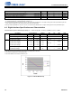
Parameter Symbol Min Typical Max Units
SCL frequency
1
1.The specification f
iicck
indicates the maximum speed of the hardware. The system designer should be aware that the actual maximum speed of the
communication port can be limited by the firmware application. Flow control using the BUSY
pin should be implemented to prevent overflow of the
input data buffer.
f
iicck
—— 400kHz
SCL low time t
iicckl
1.25 — — µs
SCL high time t
iicckh
1.25 — — µs
SCL and SDA rise time t
r
— — 75 ns
SCL and SDA fall time t
f
— — 75 ns
SCL rising to SDA rising or falling for START or STOP condition t
iicckcmd
1.25 — — µs
START condition to SCL falling t
iicstscl
1.25 — — µs
SCL falling to STOP condition t
iicstp
2.5 — — µs
Bus free time between STOP and START conditions t
iicbft
3— —µs
Setup time SDA input valid to SCL rising t
iicsu
100 — — ns
SDA input hold time after SCL falling t
iich
0— —ns
SDA output hold time from SCL falling t
hddo
— — 18 ns
SCL falling to INT
rising t
iicirqh
——3
*
DCLKP + 40 ns
NAK condition to INT
low t
iicirql
3
*
DCLKP + 20 — ns
SCL rising to BUSY
low t
iicbsyl
—3
*
DCLKP + 20 — ns
BUSY/
I2C_ SELECT
CS
CLK/SCL
MOSI
MISO/SDA
INT
0
12670
56
7
t
spicss
t
spickl
t
spickh
t
spidsu
t
spidh
t
spid ov
A6 A5 A0 R/W MSB LSB
MSB LSB
t
spicsh
t
spib syl
t
spiirql
t
spiirqh
f
spisck
t
spicsdz