
User guide

17 DS1057F1
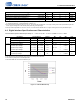
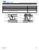
4.9 Switching Characteristics—Internal Clock
4.9 Switching Characteristics—Internal Clock
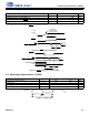
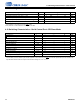
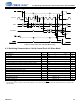
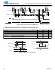
4.10 Switching Characteristics—Serial Control Port—SPI Slave Mode
Parameter Symbol Min Typ Max Unit
Internal DCLK frequency
1
(VD, VPLL = 1.2 V)
1.After initial power-on reset, F
dclk
= F
CLOCK
. After initial kick-start commands, the PLL is locked to max F
dclk
and remains locked until PLL is
reconfigured for a new setting or the next RESET
pulse.
F
dclk
F
CLOCK/
256 — 130 MHz
Internal DCLK frequency
1
(VD, VPLL = 1.0 V) F
dclk
F
CLOCK/
256 — 80 MHz
Internal DCLK period (VD, VPLL = 1.2 V) DCLKP 7.69 — 256/F
CLOCK
ns
Internal DCLK period (VD, VPLL = 1.0 V) DCLKP 12.5 — 256/F
CLOCK
ns
Cycle-to-cycle jitter on Internal DCLK or Mastered MCLK
2
2.This parameter is characterized with a VCO speed of 330 MHz.
——500—ps
Parameter Symbol Min Typical Max Units
CLK frequency
1
1.The specification f
spisck
indicates the maximum speed of the hardware. The system designer should be aware that the actual maximum speed of the
communication port can be limited by the firmware application. Flow control using the BUSY
pin should be implemented to prevent overflow of the
input data buffer. Maximum SPI clock speed is F
dclk
/2. Before locking PLL, F
dclk
= F
CLOCK
.
f
spisck
—— 25MHz
CS
falling to CLK rising t
spicss
24 — — ns
CLK low time t
spickl
20 — — ns
CLK high time t
spickh
20 — — ns
Setup time MOSI input t
spidsu
5— —ns
Hold time MOSI input t
spidh
5— —ns
CLK low to MISO output valid t
spidov
—— 11ns
CLK falling to INT
rising t
spiirqh
— — 20 ns
CS
rising to INT falling t
spiirql
0— —ns
CLK low to CS
rising t
spicsh
24 — — ns
CS
rising to MISO output high-Z t
spicsdz
—20 —ns
CLK rising to BUSY
falling t
spicbsyl
—3
*
DCLKP+20 — ns