
User guide

DS1057F1 16
4.7 Switching Characteristics—RESET
4.7 Switching Characteristics—RESET
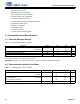
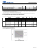
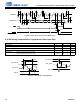
Figure 4-2. RESET Timing at Power-On
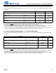
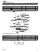
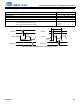
Figure 4-3. RESET
Timing after Power is Stable
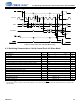
4.8 Switching Characteristics—CLOCK
Figure 4-4. CLOCK Timing
Parameter Symbol Min Max Unit
RESET
minimum pulse width low
1
1.The rising edge of RESET must not occur before the power supplies are stable at their recommended operating values. In addition, for the
configuration pins to be read correctly, the RESET
T
rstl
requirement must be met.
T
rstl
1—s
All bidirectional pins high-Z after RESET
low T
rst2z
— 100 ns
Configuration pins setup before RESET
high T
rstsu
50 — ns
Configuration pins hold after RESET
high T
rsthld
20 — ns
Parameter Symbol Min Max Unit
External clock operating frequency F
CLOCK
3.072 38.4 MHz
CLOCK period T
CLOCK
26 325 ns
CLOCK high time T
CLOCKh
45% · T
CLOCK
55% · T
CLOCK
ns
CLOCK low time T
CLOCKl
45% · T
CLOCK
55% · T
CLOCK
ns
T
rstl
T
rstsu
T
rsthld
INT
BUSY/I2C_SELECT
All supplies at
recommended
operating values.
VD,
VPLL,
VL
RESET
RESET
T
rst2z
T
rstl
T
rstsu
T
rsthld
INT
BUSY/I2C_SELECT
All Bidirectional
Pins
t
CLOCKh
T
CLOCK
CLOCK
t
CLOCKl