
User guide

DS1057F1 12
3.15 Power Management
The serial control port also includes a pin for flow control of the communications interface (BUSY/I2C_SELECT) and a pin
to indicate when the DSP has a message for the host (INT
).
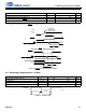
3.14.3 PLL-based Clock Generator
The low-jitter PLL generates integer or fractional multiples of a reference frequency, which are used to clock the DSP core
and peripherals. Through a second PLL divider chain, a dependent clock domain can be output on the DAO port for driving
audio converters. The CS48LV12/13 defaults to running from the external reference frequency and is switched to use the
PLL either through a boot command from the host or by the firmware running on the DSP.
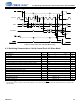
3.15 Power Management
Several control registers and bits provide independent power down control of the RAM, ROM, PLL and internal clock
domains, allowing operation in select applications with minimal power consumption. Each RAM bank (4 K word) and each
ROM bank (8 K word for code, and 4 K word for data) can be powered on or off individually. After a hardware reset, all the
memory banks are powered on.
The Host in the system can initiate a low-power mode for the DSP core to conserve system power when audio processing
is not required. The firmware API provides different levels of low-power mode, which allows each system to customize the
power consumption and wake-up protocol to its needs.
3.16 RAPID2™ Real-Time Diagnostic and Tuning Tool
This real-time interactive GUI-based program provides both control and monitoring of all critical SoundClear Voice DSP
functions. It enables users to optimize algorithmic performance to match design characteristics such as transducer type
and placement, mechanical and electrical design, and acoustic properties. It is both a system level diagnostic and tuning
tool that is used to achieve performance goals as well as industry, carrier, and OEM compliance. Its capabilities include:
• Meter monitoring including peak and clip detection for:
• Mic inputs
• Tx line out
• Rx line in
• Rx speaker out
• Dual-axis tickertape graphic monitoring
• AEC performance
• AEC input and AEC output
•Audio mode
• Mic 1 and mic 2
• Speaker out
• Line in and line out
• Automatic system-level measurements
• Bulk delay
• ENR—Echo to near-end ratio
• ERLE—Echo return loss enhanced
• Statistical measurements included
• Channel noise levels
• Channel amplitude levels
• Clip occurrences
• Real-time control of all SoundClear parameter sets
• All programmable gain amplifiers (Tx in, Tx out, Rx in, Rx out)