
Manual


Table Of Contents
- 1 Documentation Strategy
- 2 Overview
- 3 Code Overlays
- 4 Hardware Functional Description
- 5 Characteristics and Specifications
- 5.1 Absolute Maximum Ratings
- 5.2 Recommended Operations Conditions
- 5.3 Digital DC Characteristics
- 5.4 Power Supply Characteristics
- 5.5 Thermal Data (48-pin LQFP)
- 5.6 Switching Characteristics-RESET
- 5.7 Switching Characteristics-XTI
- 5.8 Switching Characteristics-Internal Clock
- 5.9 Switching Characteristics-Serial Control Port-SPI Slave Mode
- 5.10 Switching Characteristics-Serial Control Port-SPI Master Mode
- 5.11 Switching Characteristics-Serial Control Port-I2C Slave Mode
- 5.12 Switching Characteristics-Serial Control Port-I2C Master Mode
- 5.13 Switching Characteristics-Digital Audio Slave Input Port
- 5.14 Switching Characteristics-DSD Slave Input Port
- 5.15 Switching Characteristics-Digital Audio Output (DAO) Port
- 6 Ordering Information
- 7 Environmental, Manufacturing, and Handling Information
- 8 Device Pinout Diagrams
- 9 Package Mechanical Drawings
- 10 Revision History
14 DS734F5
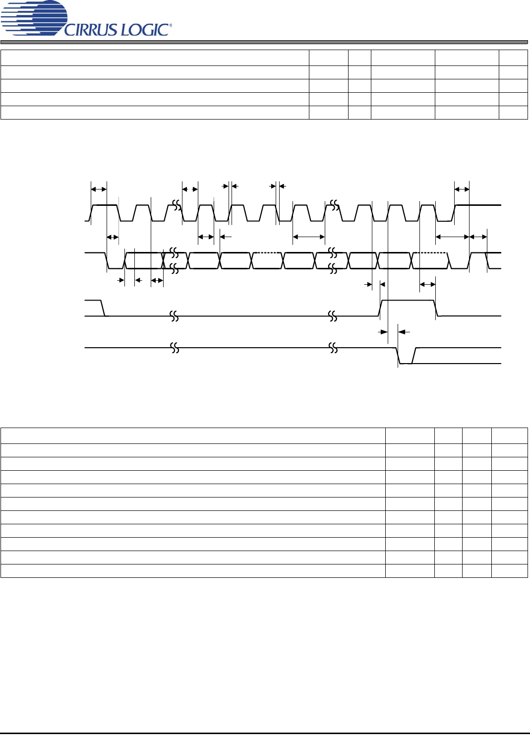
5.12 Switching Characteristics—Serial Control Port–I2C Master Mode
Figure 5-5. Serial Control Port–I
2
C Slave Mode Timing
5.12 Switching Characteristics—Serial Control Port–I
2
C Master Mode
SCP_CLK low to SCP_SDA out valid t
iicdov
— — 18 ns
SCP_CLK falling to SCP_IRQ# rising t
iicirqh
— — 3*DCLKP + 40 ns
NAK condition to SCP_IRQ# low t
iicirql
— 3*DCLKP + 20 — ns
SCP_CLK rising to SCB_BSY# low t
iicbsyl
— 3*DCLKP + 20 — ns
1.The specification f
iicck
indicates the maximum speed of the hardware. The system designer should be aware that the actual maximum speed of the
communication port may be limited by the firmware application. Flow control using the SCP_BSY# pin should be implemented to prevent overflow of
the input data buffer.
Parameter Symbol Min Max Units
SCP_CLK frequency
1
1.The specification f
iicck
indicates the maximum speed of the hardware. The system designer should be aware that the actual maximum speed of the
communication port may be limited by the firmware application.
f
iicck
—400kHz
SCP_CLK low time t
iicckl
1.25 — µs
SCP_CLK high time t
iicckh
1.25 — µs
SCP_SCK rising to SCP_SDA rising or falling for START or STOP condition t
iicckcmd
1.25 — µs
START condition to SCP_CLK falling t
iicstscl
1.25 — µs
SCP_CLK falling to STOP condition t
iicstp
2.5 — µs
Bus free time between STOP and START conditions t
iicbft
3— µs
Setup time SCP_SDA input valid to SCP_CLK rising t
iicsu
100 — ns
Hold time SCP_SDA input after SCP_CLK falling t
iich
20 — ns
SCP_CLK low to SCP_SDA out valid t
iicdov
—18 ns
Parameter Symbol Min Typical Max Units
SCP_BSY#
SCP_CLK
SCP_SDA
SCP_IRQ#
01 67801 7
t
iicckl
t
iicckh
t
iicsu
t
iich
A6 A0 R/W ACK
LSB
t
iicirqh
t
iicirql
8
ACK
MSB
t
iicstp
6
t
iiccbsyl
t
iicdov
t
iicbft
t
iicstscl
t
iicckcmd
f
iicck
t
iicckcmd
t
iicf
t
iicr