
Manual


Table Of Contents
- 1 Documentation Strategy
- 2 Overview
- 3 Code Overlays
- 4 Hardware Functional Description
- 5 Characteristics and Specifications
- 5.1 Absolute Maximum Ratings
- 5.2 Recommended Operations Conditions
- 5.3 Digital DC Characteristics
- 5.4 Power Supply Characteristics
- 5.5 Thermal Data (48-pin LQFP)
- 5.6 Switching Characteristics-RESET
- 5.7 Switching Characteristics-XTI
- 5.8 Switching Characteristics-Internal Clock
- 5.9 Switching Characteristics-Serial Control Port-SPI Slave Mode
- 5.10 Switching Characteristics-Serial Control Port-SPI Master Mode
- 5.11 Switching Characteristics-Serial Control Port-I2C Slave Mode
- 5.12 Switching Characteristics-Serial Control Port-I2C Master Mode
- 5.13 Switching Characteristics-Digital Audio Slave Input Port
- 5.14 Switching Characteristics-DSD Slave Input Port
- 5.15 Switching Characteristics-Digital Audio Output (DAO) Port
- 6 Ordering Information
- 7 Environmental, Manufacturing, and Handling Information
- 8 Device Pinout Diagrams
- 9 Package Mechanical Drawings
- 10 Revision History
13 DS734F5
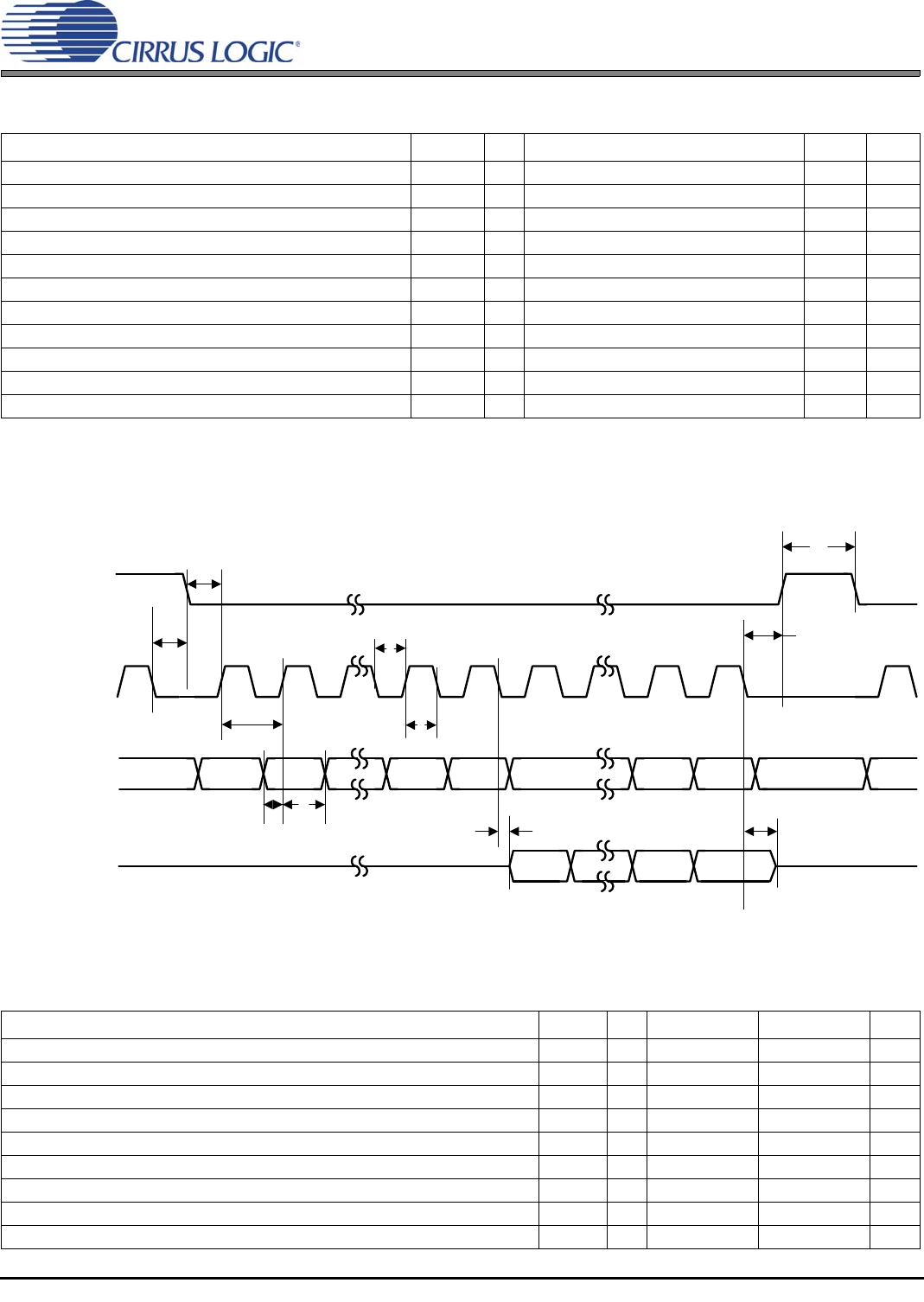
5.10 Switching Characteristics—Serial Control Port–SPI Master Mode
5.10 Switching Characteristics—Serial Control Port–SPI Master Mode
Figure 5-4. Serial Control Port–SPI Master Mode Timing
5.11 Switching Characteristics—Serial Control Port–I
2
C Slave Mode
Parameter Symbol Min Typical Max Units
SCP_CLK frequency
1
1.The specification f
spisck
indicates the maximum speed of the hardware. The system designer should be aware that the actual maximum speed of the
communication port may be limited by the firmware application.
f
spisck
——F
xtal
/2
2
2.See Section 5.7.
MHz
SCP_CS# falling to SCP_CLK rising
3
3.SCP_CLK PERIOD refers to the period of SCP_CLK as being used in a given application. It does not refer to a tested parameter.
t
spicss
— 11*DCLKP + (SCP_CLK PERIOD)/2 — ns
SCP_CLK low time t
spickl
20 — — ns
SCP_CLK high time t
spickh
20 — — ns
Setup time SCP_MISO input t
spidsu
13 — — ns
Hold time SCP_MISO input t
spidh
5— —ns
SCP_CLK low to SCP_MOSI output valid t
spidov
—— 8ns
SCP_CLK low to SCP_CS# falling t
spicsl
7— —ns
SCP_CLK low to SCP_CS# rising t
spicsh
— 11*DCLKP + (SCP_CLK PERIOD)/2 — ns
Bus free time between active SCP_CS# t
spicsx
— 3*DCLKP — ns
SCP_CLK falling to SCP_MOSI output high-Z t
spidz
— — 20 ns
Parameter Symbol Min Typical Max Units
SCP_CLK frequency
1
f
iicck
—— 400kHz
SCP_CLK low time t
iicckl
1.25 — — µs
SCP_CLK high time t
iicckh
1.25 — — µs
SCP_SCK rising to SCP_SDA rising or falling for START or STOP condition t
iicckcmd
1.25 — — µs
START condition to SCP_CLK falling t
iicstscl
1.25 — — µs
SCP_CLK falling to STOP condition t
iicstp
2.5 — — µs
Bus free time between STOP and START conditions t
iicbft
3— —µs
Setup time SCP_SDA input valid to SCP_CLK rising t
iicsu
100 — — ns
Hold time SCP_SDA input after SCP_CLK falling t
iich
20 — — ns
EE_CS#
SCP_CLK
SCP_MISO
SCP_MOSI
0
12670
56
7
t
spicss
t
spickl
t
spickh
t
spidsu
t
spidh
t
spidov
A6 A5 A0 R/W MSB LSB
MSB
LSB
t
spicsh
t
spicsx
f
spisck
t
spidz
t
spicsl