
Instruction Manual

30 DS632F1
CS44800
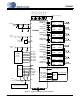
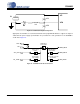
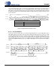
4.4.1.5 One Line Mode #2
In One Line mode #2 format, data is received most significant bit first on the first DAI_SCLK after a
DAI_LRCK transition and is valid on the rising edge of DAI_SCLK. DAI_SCLK must operate at a 256 Fs
rate. DAI_LRCK identifies the start of a new frame and is equal to the sample period. DAI_LRCK is sam-
pled as valid on the same clock edge as the most significant bit of the first data sample and must be held
high for 128 DAI_SCLK periods. Each time slot is 24 bits wide, with the valid data sample left-justified with-
in the time slot. Valid data lengths are 16, 18, 20, or 24 bits. Valid samples rates for this mode are 32 kHz
to 96 kHz.
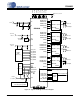
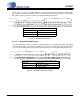
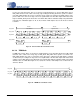
4.4.1.6 TDM Mode
In TDM mode format, data is received most significant bit first on the first DAI_SCLK after a DAI_LRCK
transition and is valid on the rising edge of DAI_SCLK. DAI_SCLK must operate at a 256 Fs rate.
DAI_LRCK identifies the start of a new frame and is equal to the sample period. DAI_LRCK is sampled
as valid on the proceeding clock edge as the most significant bit of the first data sample and must be held
valid for at least 1 DAI_SCLK period. Each time slot is 32 bits wide, with the valid data sample left-justified
within the time slot. Valid data lengths are 16, 18, 20, 24 or 32 bits. Valid samples rates for this mode are
32 kHz to 96 kHz.
PWMOUTB3
DAI_LRCK
DAI_SCLK
LSBMSB LSBMSB LSBMSB LSBMSB LSBMSB LSBMSB MSB
DAI_SDIN4
DAI_SDIN1
PWMOUTA1 PWMOUTB1PWMOUTA2 PWMOUTB2PWMOUTA3
LSBMSB LSBMSB
PWMOUTA4 PWMOUTB4
MSB
128 clks 128 clks
24 clks 24 clks
24 clks 24 clks 24 clks 24 clks 24 clks 24 clks
Left Channels Right Channels
Figure 21. One Line Mode #2 Serial Audio Format
PWMOUTB2
DAI_LRCK
DAI_SCLK
LSBMSB LSBMSB LSBMSB LSBMSB LSBMSB
DAI_SDIN1
PWMOUTA1 PWMOUTA2 PWMOUTB1PWMOUTA3
256 clks
32 clks 32 clks 32 clks 32 clks 32 clks
LSBMSB
PWMOUTB3
32 clks
LSBMSB
PWMOUTA4
32 clks
LSBMSB
PWMOUTB4
32 clks
LSB
Figure 22. TDM Mode Serial Audio Format