
Manual


DS633F1 51
CS44600
7.5 Misc. Configuration (address 04h)
7.5.1 Digital Interface Format (DIFX)
Default = 001
Function:
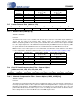
These bits select the digital interface format used for the DAI Serial Port. The required relationship be-
tween the Left/Right clock, serial clock, and serial data is defined by the Digital Interface Format and the
options are detailed in Figures 17 - 22.
7.5.2 AM Frequency Hopping (AM_FREQ_HOP)
Default = 0
Function:
Enables the modulator to alter the PWM switch timings to remove interference when the desired frequen-
cy from an AM tuner is positioned near the PWM switching rate. The PWM modulator circuitry must first
be powered down using the PDN bit in the Clock Configuration and Power Control (address 02h) Register
before this feature can be enabled. There will be a delay following the power-up sequence due to the re-
locking of the SRC. Once this feature is enabled, the output switch rate is divided by 2.25, resulting in a
lowered PWM switch rate. Care should be taken to ensure that:
PWM_MCLK / 16 > the upper frequency limit of the AM tuner used
7.5.3 Freeze Controls (FREEZE)
Default = 0
Function:
This function will freeze the previous output of, and allow modifications to be made to the Master Volume
Control (address 07h-08h), Channel XX Volume Control (address 09h-12h), and Channel Mute (address
13h) registers without the changes taking effect until the FREEZE bit is disabled. To make multiple chang-
es in these control port registers take effect simultaneously, enable the FREEZE bit, make all register
changes, then disable the FREEZE bit.
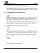
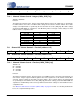
7654 3210
DIF2 DIF1 DIF0 RESERVED AM_FREQ_HOP FREEZE DEM1 DEM0
DIF2 DIF1 DIF0 Description Figure
0 0 0 Left-Justified, up to 24-bit data 18
0 0 1 I²S, up to 24-bit data 17
0 1 0 Right-Justified, 16-bit data 19
0 1 1 Right-Justified, 24-bit data 19
1 0 0 One-Line mode #1, 20-bit data 20
1 0 1 One-Line mode #2, 24-bit data 21
1 1 0 TDM Mode, up to 32-bit data 22
Table 5. Digital Audio Interface Formats